pranavkumar
Active Member
Hey DIY enthusiasts!
A very happy new year to you all!
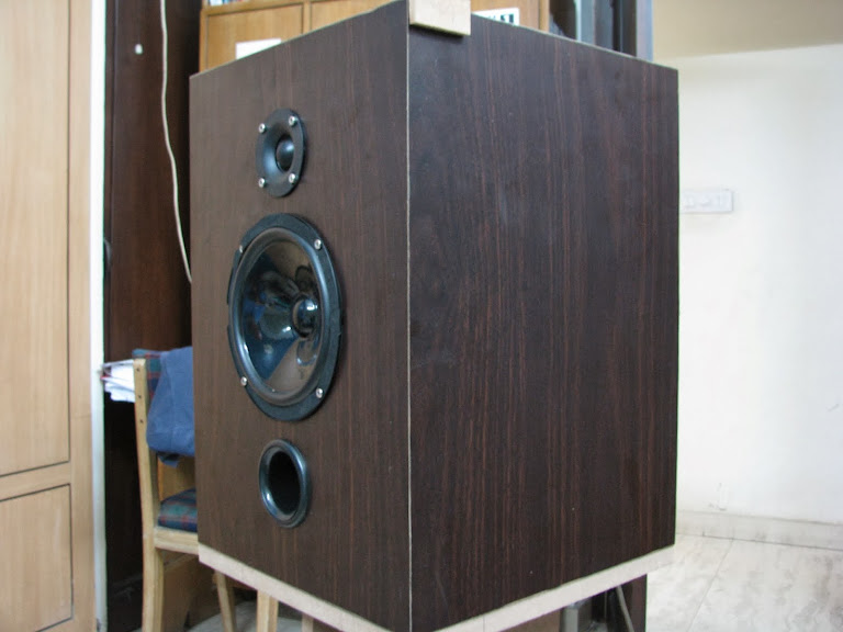
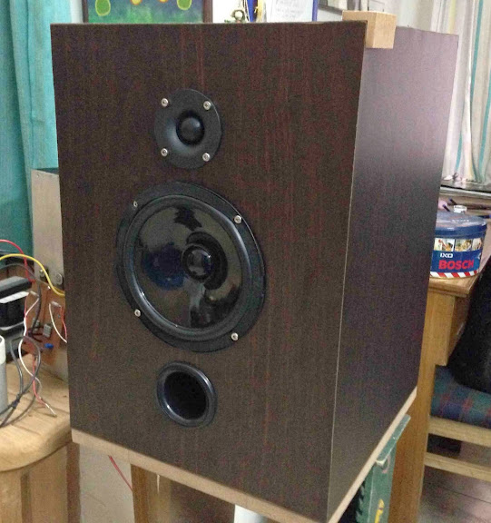
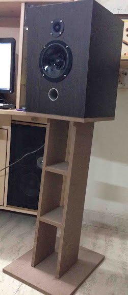
To go with the NP F5 that i recently built, i designed a pair of a little biggish bookshelves. These are simple two way ported boxes designed for peerless 6" paper cone mid bass and 25mm neodymium tweeter.
The Crossover employed is a 2 way linkwitz 2nd order XO, crossing at about 2.5kHz. Since it was a "budget" project, i used off the shelf components, which are not labelled as "Audio Grade" and they serve the purpose rather well.
I designed the box using Bass Box Pro and was able to come to a box volume of 30 Liters. Yes its not that small a box. The box is tuned at 37Hz, for a port length of 75mm. but i left the final port tuning on listening impressions.
Build:
The enclosure is built with standard 18mm MDF from green ply. Some kind of a brace was necessary since the box was big, and there was clear scope of wall resonances.
It passed the "knock" test fairly well!
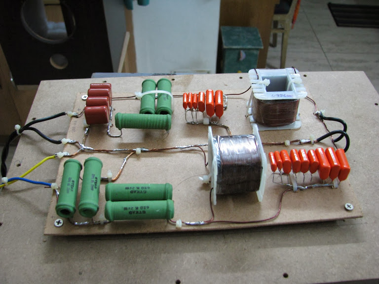
Crossover:
The crossover is a simple 2nd order crossover, satisfying the linkwitz criterion.
I used Vishay's Metalized Polypropylene caps. Since the maximum capacity available was 2.2uF, i had to make banks to come to a final value.
The resistors are standard wirewound 10W resistors, used in series and parallel combinations.
The inductors are would with 19 gauge bell wire. would by a local trafo winder.
Drivers:
S16NI : Its a 6" paper cone driver, capable to handle about 25W of power. Which is pretty decent in my opinion. It goes pretty low as well, without compromising the lower mids. The only thing i didnt like was the construction. These could have been sturdier.
TL25SN: Brilliant neodymium tweeters, a little expensive, but well worth the price.
These speakers sounded brilliant with the F5. The 6" speakers could handle the power from the amplifier very well (Better than i had imagined). The Low's were very distinct, clear and tight. The credit there goes to the fairly high damping factor of the F5 as well.
Mids were subtle and didnt overpower the lows or the highs and the highs were articulate and expressive, with a distinct character.
Here are some pictures:


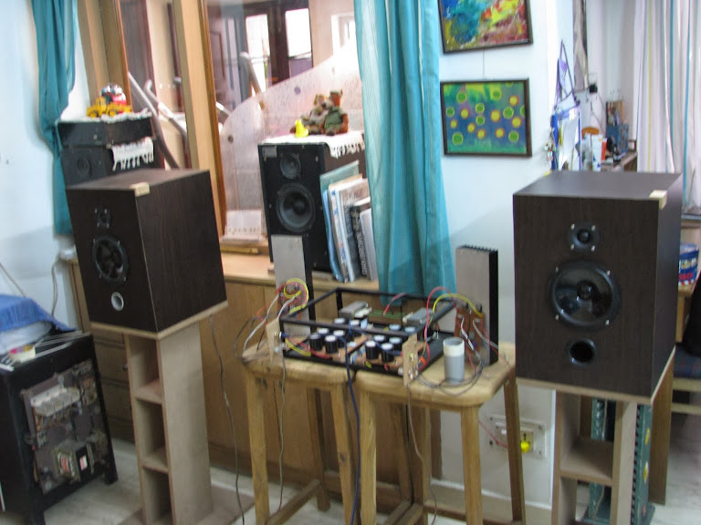
better pictures to come soon")
A very happy new year to you all!
To go with the NP F5 that i recently built, i designed a pair of a little biggish bookshelves. These are simple two way ported boxes designed for peerless 6" paper cone mid bass and 25mm neodymium tweeter.
The Crossover employed is a 2 way linkwitz 2nd order XO, crossing at about 2.5kHz. Since it was a "budget" project, i used off the shelf components, which are not labelled as "Audio Grade" and they serve the purpose rather well.
I designed the box using Bass Box Pro and was able to come to a box volume of 30 Liters. Yes its not that small a box. The box is tuned at 37Hz, for a port length of 75mm. but i left the final port tuning on listening impressions.
Build:
The enclosure is built with standard 18mm MDF from green ply. Some kind of a brace was necessary since the box was big, and there was clear scope of wall resonances.
It passed the "knock" test fairly well!
Crossover:
The crossover is a simple 2nd order crossover, satisfying the linkwitz criterion.
I used Vishay's Metalized Polypropylene caps. Since the maximum capacity available was 2.2uF, i had to make banks to come to a final value.
The resistors are standard wirewound 10W resistors, used in series and parallel combinations.
The inductors are would with 19 gauge bell wire. would by a local trafo winder.
Drivers:
S16NI : Its a 6" paper cone driver, capable to handle about 25W of power. Which is pretty decent in my opinion. It goes pretty low as well, without compromising the lower mids. The only thing i didnt like was the construction. These could have been sturdier.
TL25SN: Brilliant neodymium tweeters, a little expensive, but well worth the price.
These speakers sounded brilliant with the F5. The 6" speakers could handle the power from the amplifier very well (Better than i had imagined). The Low's were very distinct, clear and tight. The credit there goes to the fairly high damping factor of the F5 as well.
Mids were subtle and didnt overpower the lows or the highs and the highs were articulate and expressive, with a distinct character.
Here are some pictures:
better pictures to come soon