DIY Amplifier gets new DIY Power Supply

omishra

Well-Known Member
Joined
May 31, 2011
Messages
2,357
Points
113
Location
Pune
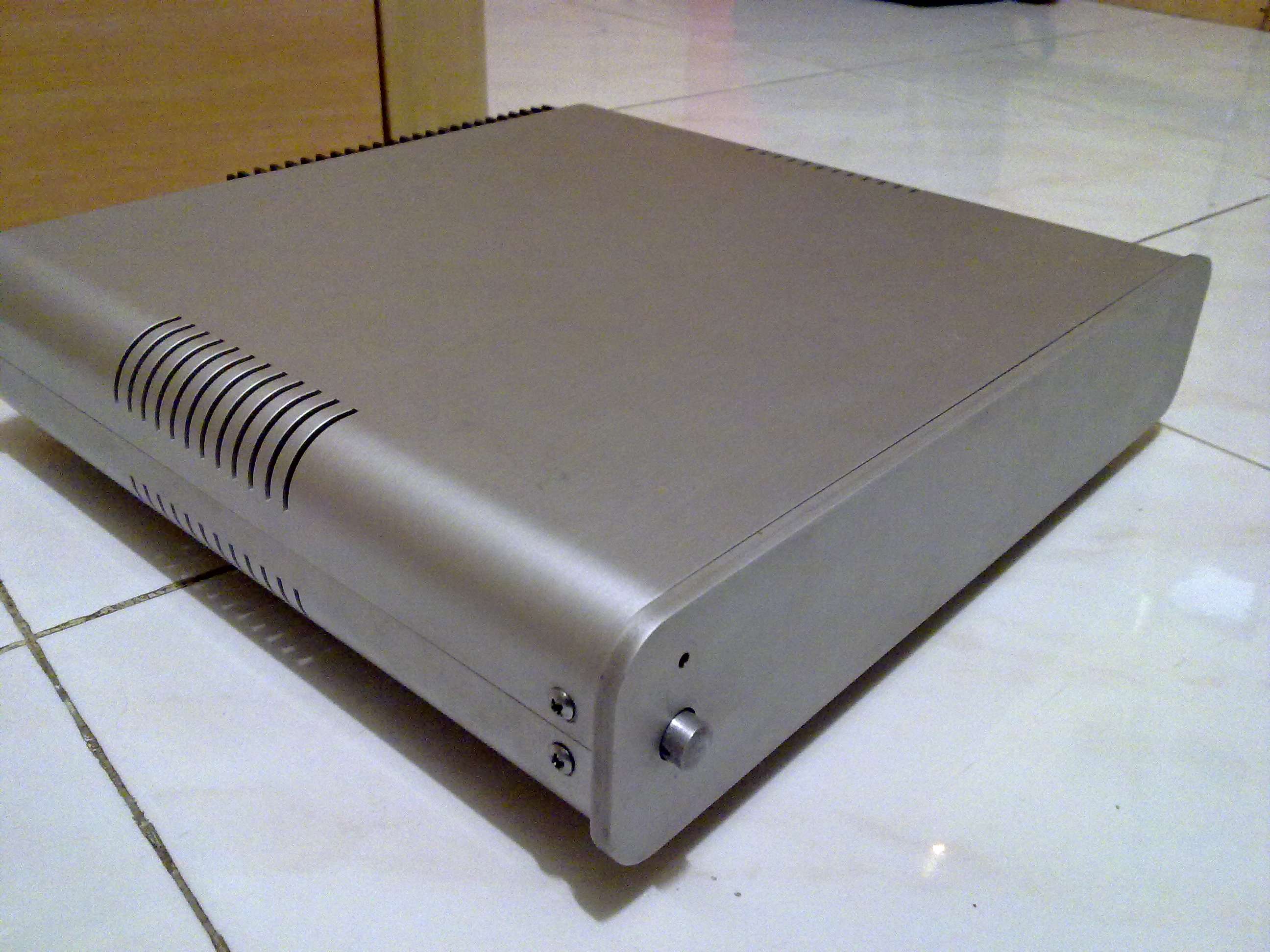
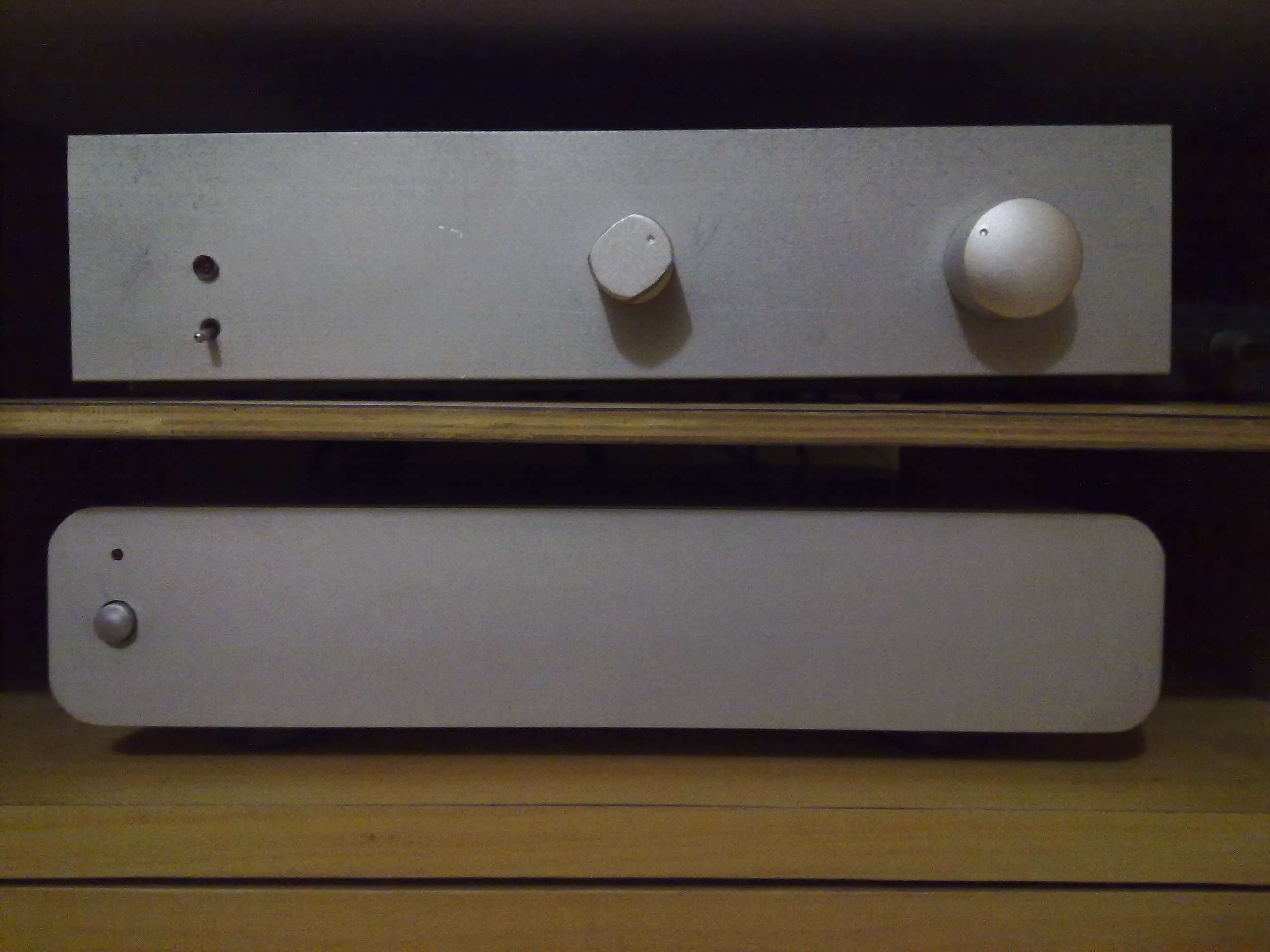
Here I am showcasing my DIY class AB amplifier which I am using as my main stereo Amp. This is one of the excellent sounding, neutral analog amp which I build in 2005. Now I am using this continuously since last 1 year. Few forum member listened to this.
  • All circuits are home made, PCBs are self designed.
  • Main amplifier and protection boards are home made including etching at home
  • Few turns of 24SWG enameled copper wire wound over toroidal to get extra 12-0-12 supply.
  • Voltage gain of the original amplifier design referenced below is reduced. Now in place of 200mV, after modification 650mV input will get max output.
  • With my experimentation changed few caps including input signal cap.
  • Continuous power into 4 ohms is well excess of 40W RMS per channel.
  • Each channel has floating ground referenced to central star connection.
  • chassis is connected to earth ground.

image721.jpg


Reference circuit -
25 Watt MosFet Audio Amplifier - RED - Page2
Facts and Figures - RED

Recently new Power Supply added for this.
  • Used two secondaries of one toroidal transformer (22-0, 22-0, 6.6A each).
  • By rectifying with separate bridge rectifiers each power line passes through 100nF,100V metal polyester caps.
  • Again it uses 0.47ohms,5W in series to make CRC
  • fuse protects all.
  • Transformer mains also have DC protection and fuse for current withdraw. Also 33 ohm NTC inline to AC mains.
  • Amplifier Ground is derived from connecting +ve of one output to -ve of another.
  • Both channels PS is separate with common transformer.
  • Bleeder is in place and snubber is not added.

Speaker protection -
  • Delayed connection after power ON to avoid TURN on pop- 3 sec
  • Instant disconnection after power OFF avoids pops.
  • DC detection for less than 3Hz, >1.0V and DC 1.0V on speaker wires.
  • Buzzer beep for DC detection and speakers disconnect instantly.

image720y.jpg


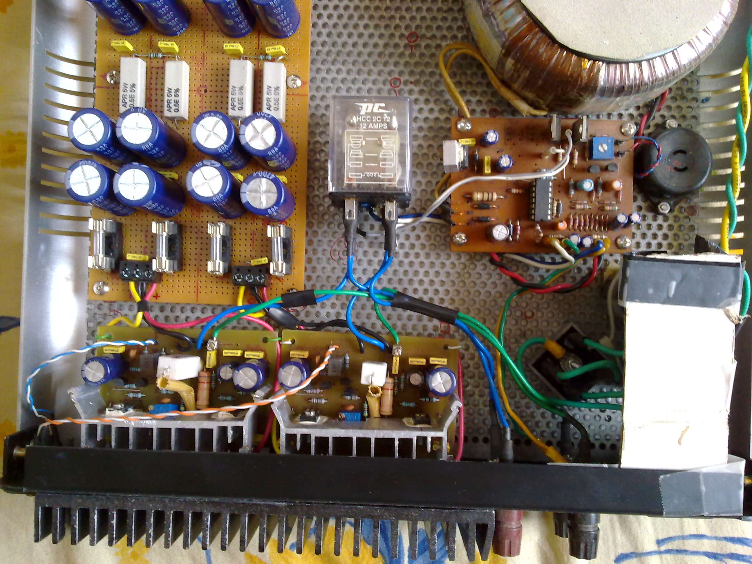
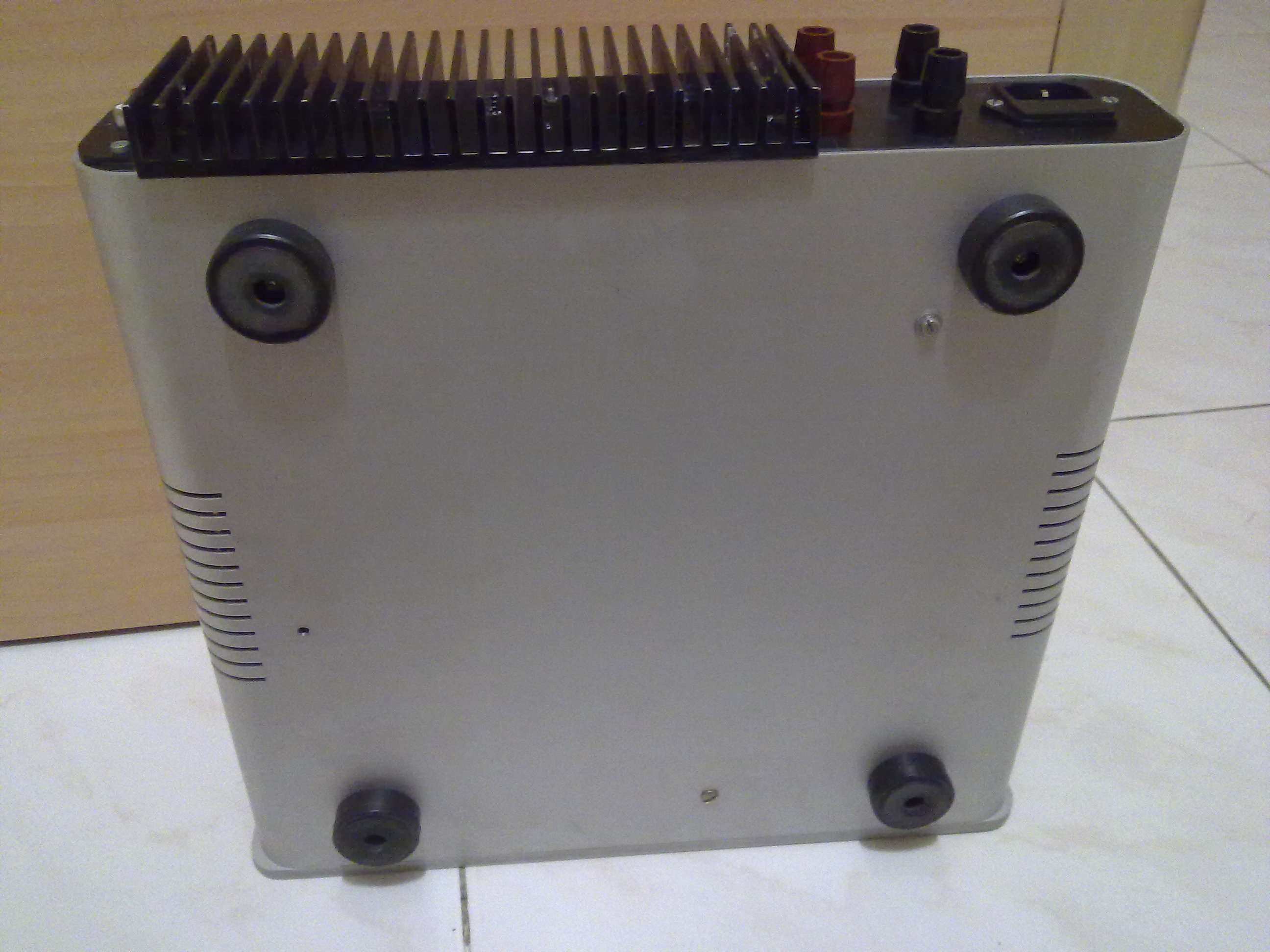
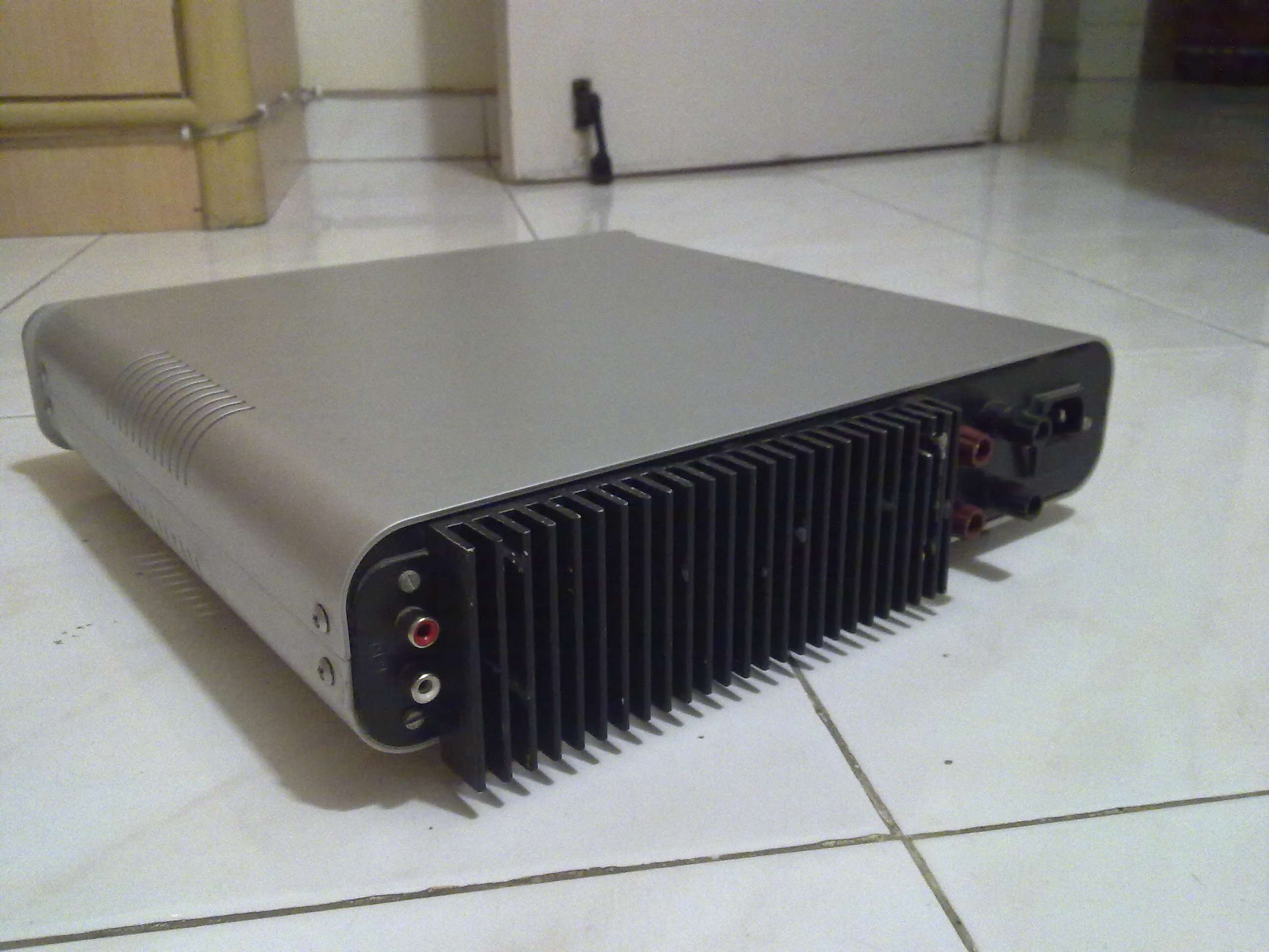
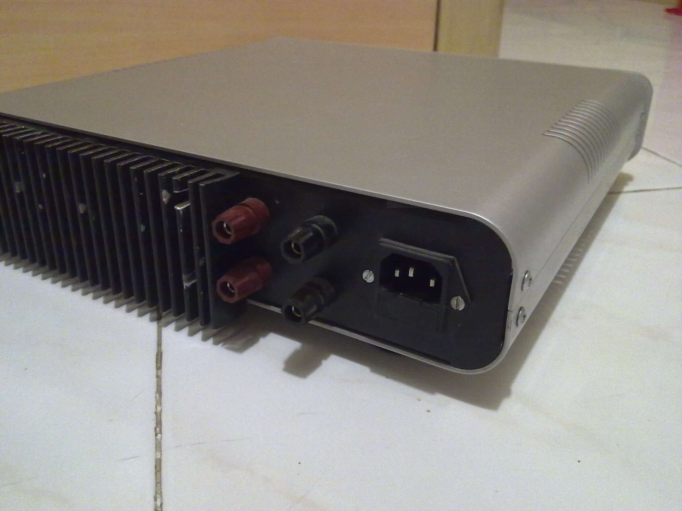
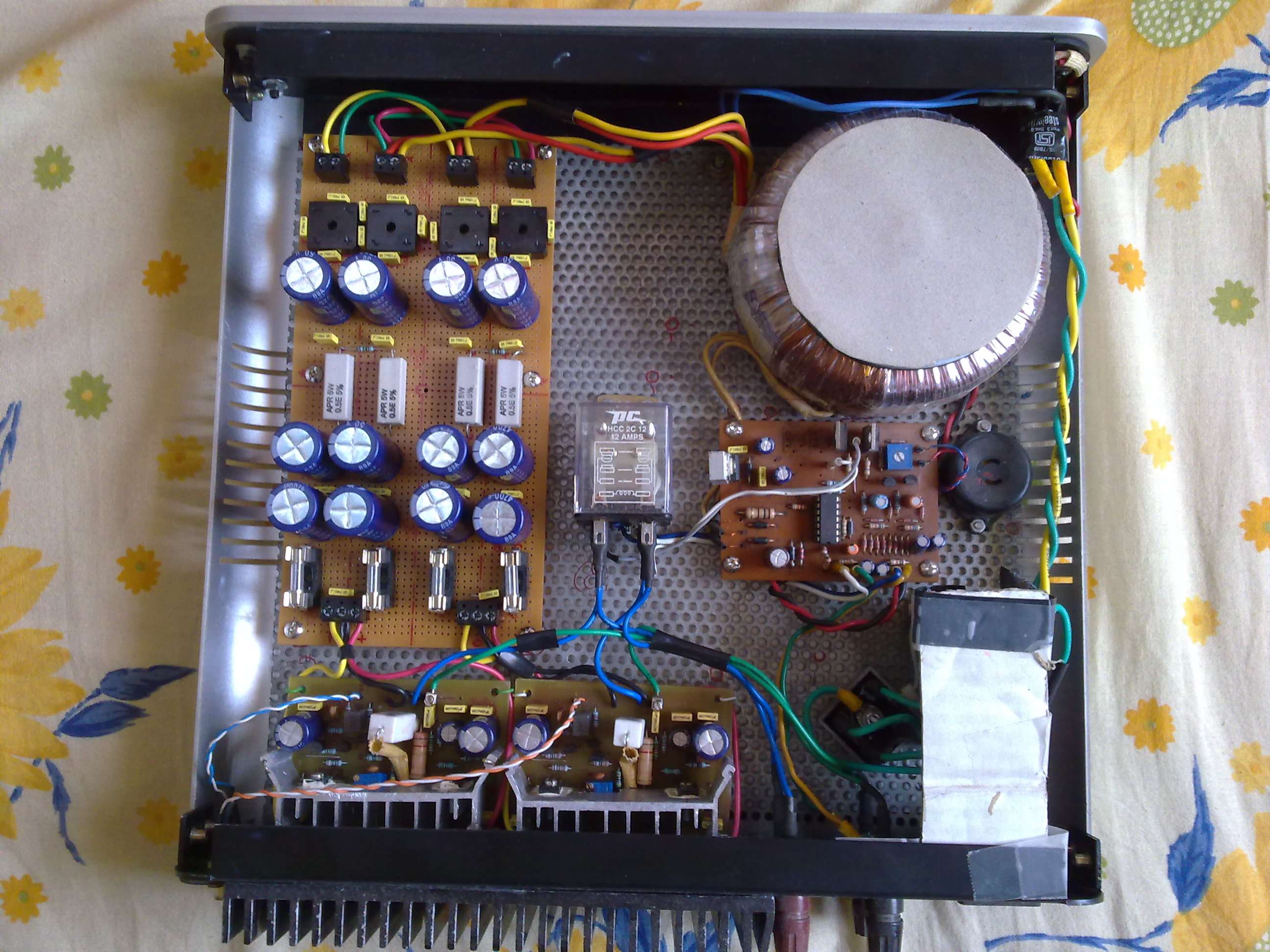
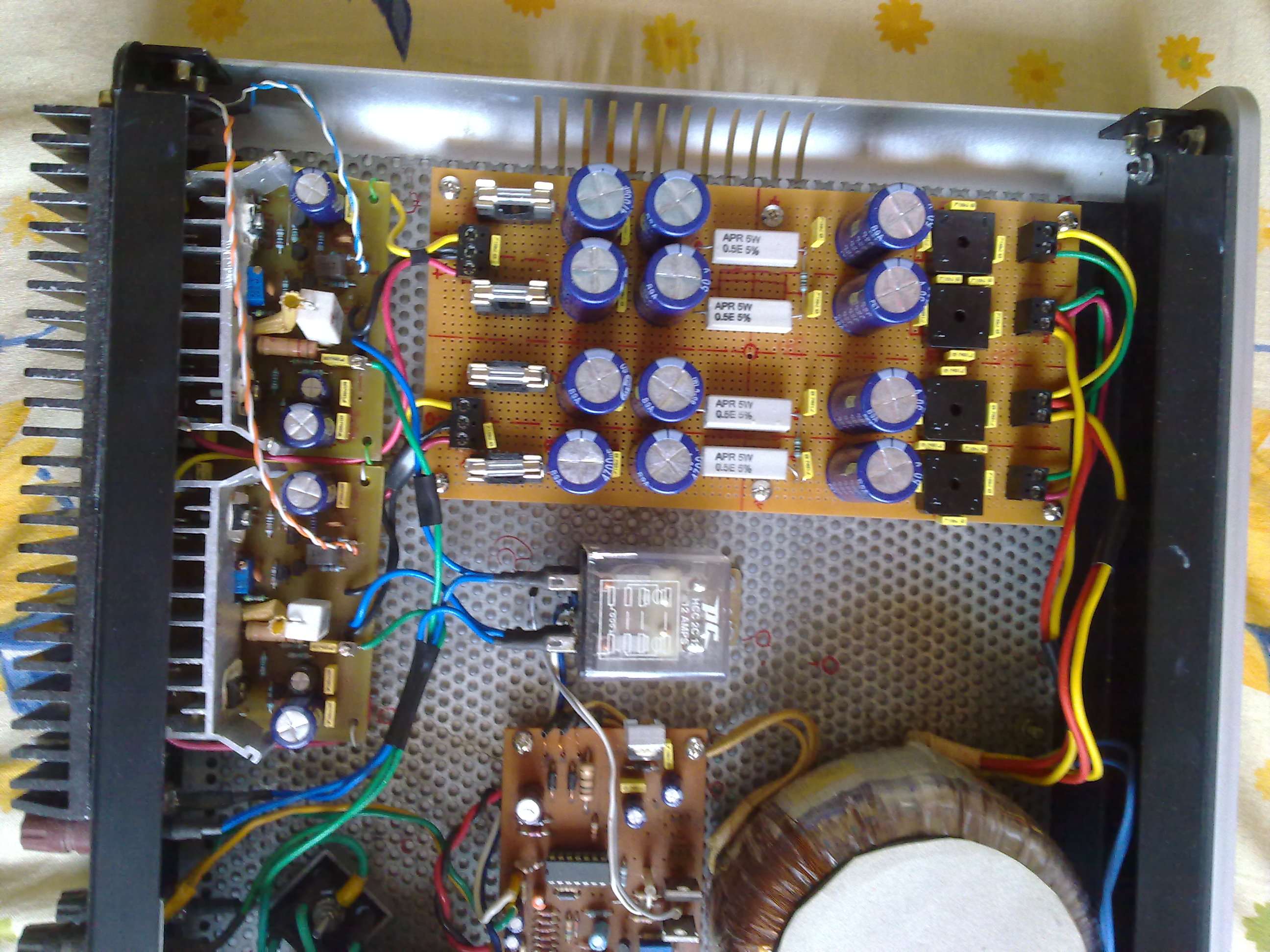
Another view for layout.

image719.jpg
 
Good layout. and wiring. I like the chassis. I guess with the perforated base you get ventilation as well as holes for your pcb's. Is that what you have done?. It would be nice if you can add a picture of the DIY completed.I mean with the covers.

:clapping:
 
Last edited:
Good layout. and wiring. I like the chassis. I guess with the perforated base you get ventilation as well as holes for your pcb's. Is that what you have done?. It would be nice if you can add a picture of the DIY completed.I mean with the covers.

:clapping:

Hi Gopi,

Thanks. That perforated board is only for PCB mounting and avoiding extra holes in chassis. Ventilation is sidewise. I cut rear panel to mount heatsink.

My amp cabinets were sourced from Thailand. Unfortunately that guy moved away from business. Now I am just finished all inventory which I acquired in the past.

Here are more pics.
Bottom side mounted with 3 heavy nut bolts.
image723i.jpg


image724o.jpg

image725.jpg

image726.jpg


In action -
image728.jpg
 
Last edited:
Nicely done. Which is the delay circuit, can you point it out fromt he photos? Done locally? If yes, I am interested in knowing more, I need one for a preamp.
 
Nicely done. Which is the delay circuit, can you point it out fromt he photos? Done locally? If yes, I am interested in knowing more, I need one for a preamp.

Delay circuit is near the toroidal between Relay and buzzer. Yes it was done locally and got couple of PCBs from OM electronics, SP road while I was there. If you are interested then I will pass on details. It was done long time back and has chain of 3 timers in series using NAND cmos chip 40xx which starts one after another. and each timers logic operate power transistor as switch. I first step timer to start on delay of 3 sec.

I need to dog into desktop for files. I surely have backed up.
 
I like this delay timer as it counts AC mains cycles for the delay.
The timing chart shown is for 50Hz mains.

Caution - as drawn, it is directly powered off the mains, but it should be
simple to power it off a lower voltage tap (6V ac, for eg) and use a relay of the
appropriate voltage.

20096152255697.gif
 
Last edited:
Added above links for you references.

protection_1.gif


R1-2=See text* D1-4= 1N4007
R3=470R 1W*see text D5-8= 1N4148
R4-5= 1M D9=12V 1.2W Zener
R6-7= 1K D10-22= 1N4148
R8-14= 15K LD1-2= LED
R9-15= 56K LD3=Flash Led [RED]
R10-16= 56K BZ= BUZZER 12V
R11-17= 10K J1-4= Connectors
R12-13= 39K TR1= 10K Trimmer
R18= 39K RL1-3= 12V 2X2(10A)RELAY
R19= 1K2
R20= 1K
R21-22= 3K9
R23= 22K
R24= 39K
RX= 47R 10W
C1= 220uF 63V
C2-5= 47uF 63V
C3-4=100nF
C6= 1uF 25V
C7= 4.7uF 25V
C8= 470uF 16V
C9-14= 22uF 16V
C10-13= 33uF 63V
CX= 33nF 630V
IC1= 4093 cmos
IC2= 7812T
Q1-4= BD679 or 2N5294
Q5-6= BC550C
 
Last edited:
Very clean and neat DIY amplifier build. Only one question when some component of project behave erratically how do you debug it? Your all DIY is very clean and quality build. :clapping:

I read your pre-amp update of SX4 head-unit in some other forum few years back. After that, I understood that you have exceptional knowledge of electronics.

Electronics was also my hobby since childhood. I was making circuits after seeing simple circuits designs in "Electronics For You" but could not take it advance step.

Thanks Anuj for kind words. I have no exceptional knowledge but I never forget the basic. I try to refresh details of every bit and it is required everywhere in all electronics I see. Yes that SX4 mod was published in team-bhp forum.

http://www.team-bhp.com/forum/diy-do-yourself/43442-sx4-oem-hu-pass-surgery-amp-section.html
http://www.team-bhp.com/forum/diy-do-yourself/43442-sx4-oem-hu-pass-surgery-amp-section-4.html

Regarding debug, I get test points calculated at certain voltage/current and try to get near to that by measuring. If not then there is some problem around it. Also I have small 5Mhz oscilloscope for waveform purpose.
 
Last edited:
SX4 OEM HU: By pass surgery for Amp section - Team-BHP
SX4 OEM HU: By pass surgery for Amp section - Page 4 - Team-BHP

Regarding debug, I get test points calculated at certain voltage/current and try to get near to that by measuring. If not then there is some problem around it. Also I have small 5Mhz oscilloscope for waveform purpose.

That's the most amazing surgery I have seen. Looks like lot of us in HiFivision are in Team BHP too. Looks like love for Music Cars go hand in hand ? Would love to know how many of us are in Team BHP too. How did you eliminate alternator whine in your setup? I have this problem when I feed power to my IPOD dock which I have connected to my vehicle's HU.
 
Last edited:
A beautiful, well-constructed speaker with class-leading soundstage, imaging and bass that is fast, deep, and precise.
Back
Top