Experiments in speaker design for cardioid radiation pattern

Vineethkumar01

Well-Known Member
Joined
May 19, 2015
Messages
483
Points
93
Location
Bangalore
Recent discussions over in this forum and over at diyaudio reignited my interest in cardioid speakers. So I thought why not create a thread for it, apply little brainstorming and try to build one (the first prototype).. :D
With recent advances in BEM simulations using ATH software, mabat has presented some very interesting sims on how to make cardioid radiation pattern with woofers with a very simple design. The original discussion is available around here:

Recently mabat gave me some ideas for a 5-inch driver-based prototype design. The design is scalable to higher radius drivers.
Let's see if the idea works out or not.. :)
I am reposting mabat's ideas and simulation results here.
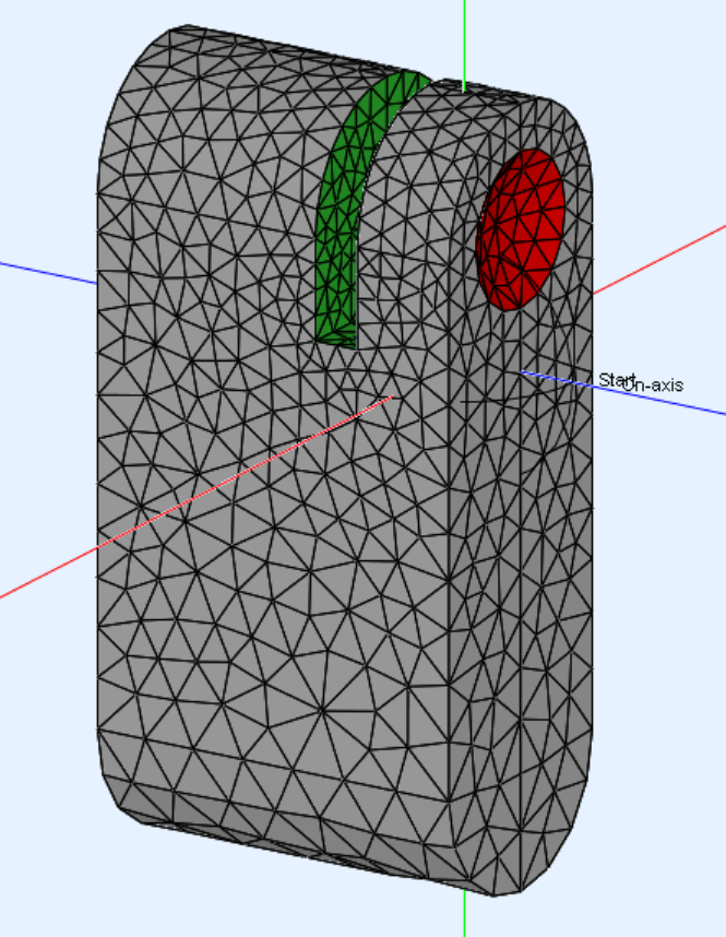
Cabinet design for the woofer (red colored portion in below pic is the driver ):
1674411825640-png.1133532

bee0-wide-h-png.1133535

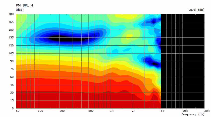
horizontal directivity
wide-h-jpg.1133536

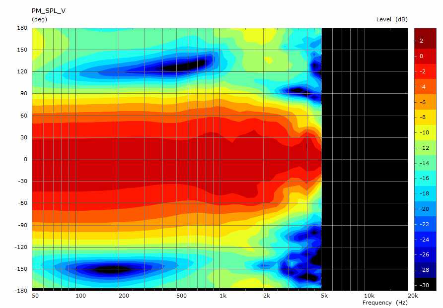
Vertical directivity
wide-w-jpg.1133537

The kind of final design concept that mabat likes at the moment look like the following:
1682520850669.jpeg
Cardioid mids+matching horn on top+properly integrated subwoofer for the lowest frequencies

For now let's start with an xps foam prototype box and some measurements :D
if it works out, we can think about a real build.. :)
 
The concept scaled to a cardioid implementation with 15inch woofer, corresponding BEM simulation results and comparison with a monopole 15inch woofer (Again, all these are mabat's simulation results)
Monopole 15 inch woofer in cabinet
bee15-mesh-mono-png.1134449


Corresponding BEM simulation results for a lot of things, including directivity
bee15-png.1134450

15inch woofer in a 'cardioidish' kind of cabinet as described above
bee15-mesh-ported-png.1134452


Corresponding BEM sim results
bee15-ported-png.1134453


Compare the first plot in the above plots (monopole vs cardioid).. Look at the directivity control down to 50 Hz in both cases..
Isn't it fascinating...? 🤩
 
I am posting details of my current system here just for a reference
My current system is DSP active 2/2.5 way system with 2 x Satori WO24P-8s per side and an ST260 KVAR horn attached to a BMS 4550 compression driver
Here is my system playing (Youtube video doesn't do much justice, so this recording is just for fun) before I applied room EQ to the system :D

Here are its crossover & measurements in a 2-way configuration:
1679125961136-png.1154957

Full measured polars & spin data
1679125970988-png.1154958

Phase response of the system is the grey line in the first graph above 😀
Step response of the system. 😎
1679125988501-png.1154959

Olive preference score (for fun) :D
1679126057738-png.1154960


Here is the highlight factor of the system (zoomed in horizontal polars from 1kHz to 20kHz)
1677905516104-png.1149501

Nearly constant (slightly rising) directivity index from about 1kHz and up 😎

Speaker response at listening position after room EQ with frequency-dependent windowing and full FIR EQ (measurements before & after room EQ)
1679506181023-png.1156497


Step responses at listening position
1679506321941-png.1156501


I guess I will stop with this for now..:p Time to focus on building a cardioid speaker🤓
Ohh.. and by the way the above system is what @aeroash heard at my home when he visited recently 😉
Very nice sounding you tube content good sir ' uyierm niyae 🎶🎶🎶🎶👌👌👌
 
I am posting details of my current system here just for a reference
My current system is DSP active 2/2.5 way system with 2 x Satori WO24P-8s per side and an ST260 KVAR horn attached to a BMS 4550 compression driver
Here is my system playing (Youtube video doesn't do much justice, so this recording is just for fun) before I applied room EQ to the system :D

Here are its crossover & measurements in a 2-way configuration:
1679125961136-png.1154957

Full measured polars & spin data
1679125970988-png.1154958

Phase response of the system is the grey line in the first graph above 😀
Step response of the system. 😎
1679125988501-png.1154959

Olive preference score (for fun) :D
1679126057738-png.1154960


Here is the highlight factor of the system (zoomed in horizontal polars from 1kHz to 20kHz)
1677905516104-png.1149501

Nearly constant (slightly rising) directivity index from about 1kHz and up 😎

Speaker response at listening position after room EQ with frequency-dependent windowing and full FIR EQ (measurements before & after room EQ)
1679506181023-png.1156497


Step responses at listening position
1679506321941-png.1156501


I guess I will stop with this for now..:p Time to focus on building a cardioid speaker🤓
Ohh.. and by the way the above system is what @aeroash heard at my home when he visited recently 😉
Imo, Looking at the step the highs look a bit more delayed by around 100usec. It would be interesting to see the step once again after you move the HF horn ahead by around 3.4cm.
 
Imo, Looking at the step the highs look a bit more delayed by around 100usec. It would be interesting to see the step once again after you move the HF horn ahead by around 3.4cm.
I thought it was the lows that were delayed by a minute amount. It could be.
The crossover linearization FIR filter is approximate and not exact, and the delay dialled in was not pinpoint precise.
These will affect the step response by a some amount.. :)
Given that the current state of these speakers is as below (disassembled and in parts), I wont be able to measure any of it anytime soon.. :D
img20230422153219-jpg.1167487


But since VituixCAD sims are very accurate, I can show the effect of a 100ms timing advance applied on the horn branch.
Here is that delay applied in horn branch
1682666460657.png


Here is the spin data
1682666519695.png

And here is the new step response:
1682666551765.png
 
I am posting details of my current system here just for a reference
My current system is DSP active 2/2.5 way system with 2 x Satori WO24P-8s per side and an ST260 KVAR horn attached to a BMS 4550 compression driver
Here is my system playing (Youtube video doesn't do much justice, so this recording is just for fun) before I applied room EQ to the system :D

Here are its crossover & measurements in a 2-way configuration:
1679125961136-png.1154957

Full measured polars & spin data
1679125970988-png.1154958

Phase response of the system is the grey line in the first graph above 😀
Step response of the system. 😎
1679125988501-png.1154959

Olive preference score (for fun) :D
1679126057738-png.1154960


Here is the highlight factor of the system (zoomed in horizontal polars from 1kHz to 20kHz)
1677905516104-png.1149501

Nearly constant (slightly rising) directivity index from about 1kHz and up 😎

Speaker response at listening position after room EQ with frequency-dependent windowing and full FIR EQ (measurements before & after room EQ)
1679506181023-png.1156497


Step responses at listening position
1679506321941-png.1156501


I guess I will stop with this for now..:p Time to focus on building a cardioid speaker🤓
Ohh.. and by the way the above system is what @aeroash heard at my home when he visited recently 😉
Imo, Looking at the step the highs look a bit more delayed by around 100usec. It would be interesting to see the step once again after you move the HF horn ahead by around 3.4cm.
I thought it was the lows that were delayed by a minute amount. It could be.
The crossover linearization FIR filter is approximate and not exact, and the delay dialled in was not pinpoint precise.
These will affect the step response by a some amount.. :)
Given that the current state of these speakers is as below (disassembled and in parts), I wont be able to measure any of it anytime soon.. :D
img20230422153219-jpg.1167487


But since VituixCAD sims are very accurate, I can show the effect of a 100ms timing advance applied on the horn branch.
Here is that delay applied in horn branch
View attachment 76700


Here is the spin data
View attachment 76701

And here is the new step response:
View attachment 76702
The simulation was not an issue as seen in post #4, but the measured Response was showing more delay in HF. I had asked for 100usec of delay and not 100msec.
 
Imo, Looking at the step the highs look a bit more delayed by around 100usec. It would be interesting to see the step once again after you move the HF horn ahead by around 3.4cm.
The VituixCad simulation I showed above is not just "a simulation". It is showing how the measured polar responses, other derived parameters from them etc change with variations in the signal processing blocks applied to the driver inputs. And once the measured data supplied to the program is accurate one can change relative driver orientations in the x, y and z planes and more and see its effects effects on the response in time and frequency domains very accurately.

If you look at the branch of the crossover connected to the BMS 4550 driver in the above crossover pic, you can see that just before the driver and capacitor, there is a block called A1 which shows a -100us delay applied. The corresponding impact on the step response is showed in the pic right below it. So even if i go and physically measure it again, to a high degree of confidence, the step response will look like the response I have shown
The simulation was not an issue as seen in post #4, but the measured Response was showing more delay in HF. I had asked for 100usec of delay and not 100msec.
It is a typo on my part. If you look at the crossover branch of the tweeter, you can see that I applied 100us and not 100ms advance in time.
 
Without wasting more time, let's get back to business... :D

First prototype of the concept using a 5inch SICA coaxial driver being measured:
1683190889987.png
The slot is undamped. So it is bare driver+cabinet

Full horizontal polar measurements upto 180 degrees:
1683045824668-png.1170488


We have dipole-like directivity (above fancy looking Directivity plot) below 1kHz. But nasty resonances around 1.25kHz. This is not good.
Here is the comparison between BEM simulations and real world results for the 'no damping' case above:

BEM sim results
1683083630955-png.1170650


Real measurements as shown above
1683083672941-png.1170654


Pretty close.. if you ask me.. :D
So we have some confidence now to proceed
 
Round-2: Partially damped slot behind the driver

1683122614166-png.1170756


Polar measurement-taking action
1683122669736-png.1170757


Measurement results
1683122460632-png.1170755


We are better now.. we have dipole radiation restricted to less than 500 Hz now and the pesky 1.5kHz resonance reduced.. Confidence inspiring to move forward.. :D
 
Round-3: Full damping of slot behind the driver
1683133795544-png.1170828

Measurements
1683133842026-png.1170829

There we have it folks.. :D :D Full range cardioid constant directivity.. Pretty exciting if you ask me...
Such a simple concept and build but very nice results.. :)

So That's it. We have achieved the objective of this experiment. That is to achieve full range carioid behaviour in the passband of the woofer. SInce this is a coaxial driver, the tweeter directivity can be blended with the woofer's around 2.5kHz to create a full range cardioidish behaviour.
Here is the tweeter response from round-1 (so Ignore everything below about 600Hz):
1683044730413-png.1170486

But to help the driver I will make it a 3-way and crossover to an omni woofer below 200-300 Hz :)
 
To put the final nails on the coffin of the closed box.. :p

BEM simulation of closed box cabinet of the above dimensions
monpole_box.jpg

Horizontal polars

monpole_box_H_polars.jpg


Cardioid box
cardioid_box.jpg

Horizontal polars
cardioid_box_H_polars.jpg

Here are the actual measurement comparison of the on-axis response of my Sica coax driver in a teardrop-shaped closed box vs cardioid box
ignore the light blue line. Dark blue is teardrop box. Brown is the cardioid box. The wiggles around 600Hz to 1.2kHz are resonances due to the foam box construction and will vanish in a proper build
on_axis_compare.jpg

Summary
Cardioid box not only gives awesome-looking polars and eliminates pesky midrange resonances but it will also yield a gain in response on axis of the order of few dBs, thereby helping with reducing baffle step compared to any similar dimensional sealed/ported box... This is probably due to the constructive interference between the radiation from the leaking port and that from the driver. Hence the need for equalization is less in the midrange up to about 200Hz, below which a monopole woofer takes over.

All in all a win-win situation.. :D
 
For excellent sound that won't break the bank, the 5 Star Award Winning Wharfedale Diamond 12.1 Bookshelf Speakers is the one to consider!
Back
Top