Myref Evo-2 Build

avesbilal

Active Member
Joined
Jun 23, 2014
Messages
151
Points
43
Location
Hyderabad
Myref Evo-2 Build

Starting a thread on Myref Evo-2 build which I started yesterday.

First I want to thank Linuxguru for providing me this Kit and his hard work on improving this Amp, Not to forget Mauro Penasa a big thank you to him for designing this Amp and contributing it to DIY Community.
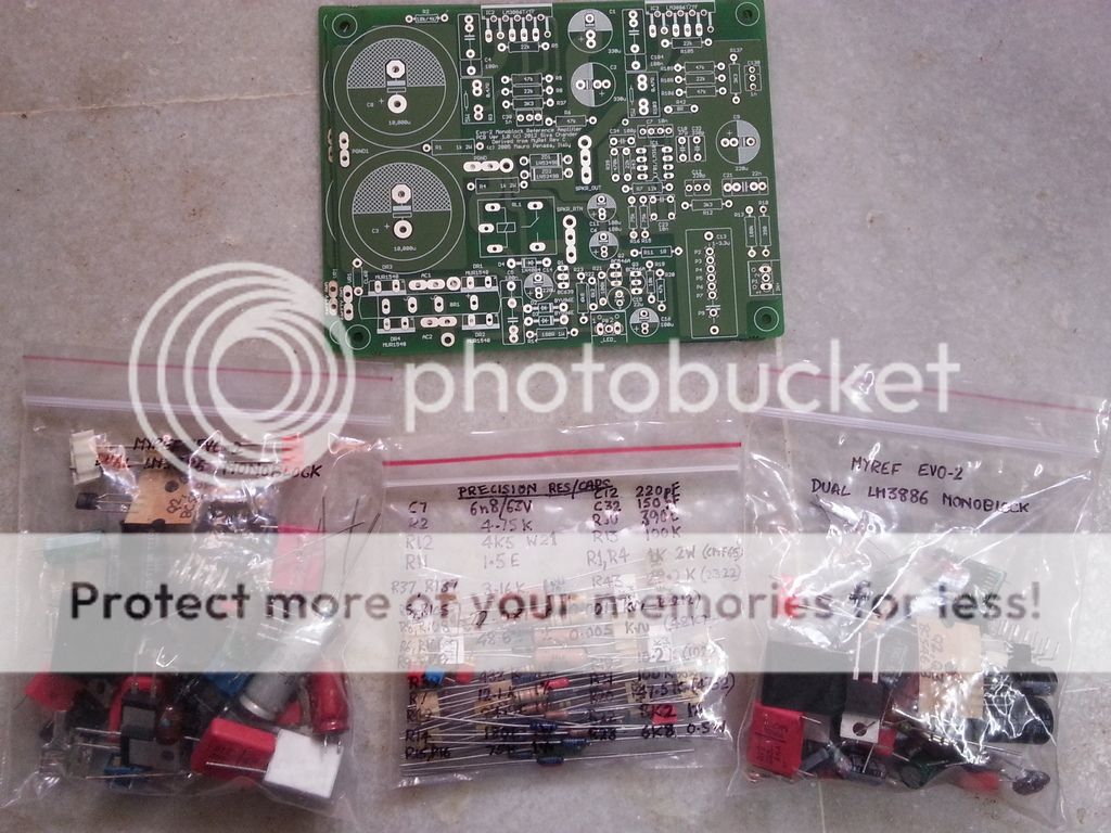
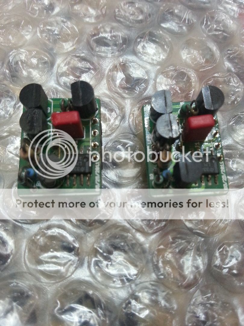
KIT and PCB
20160319_151136_zps8vfrdy2l.jpg

20160320_161010_zpsm4bs995x.jpg


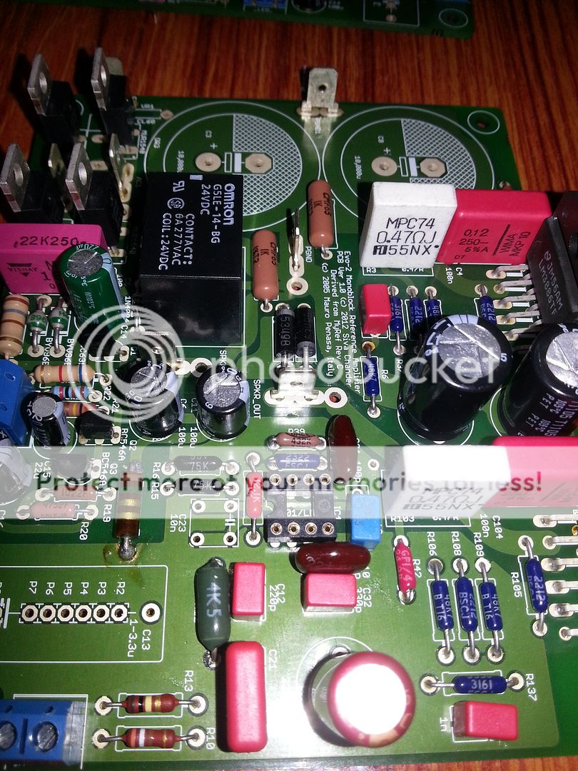
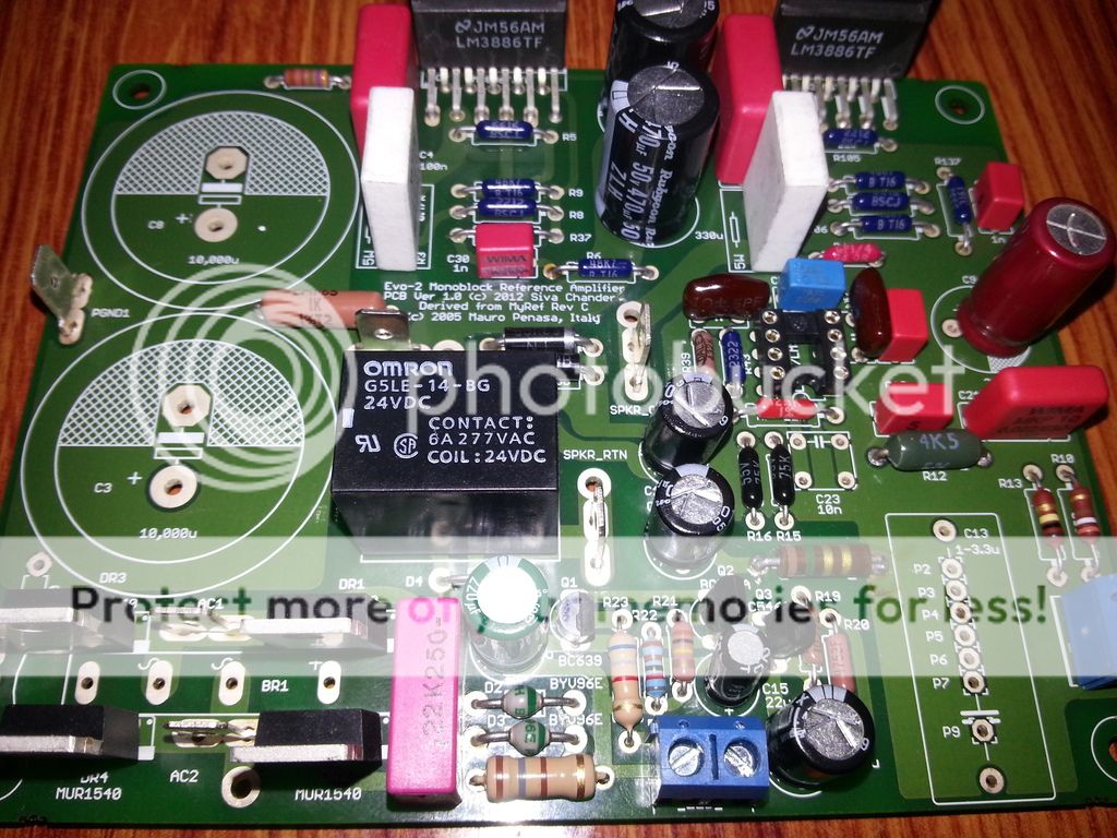
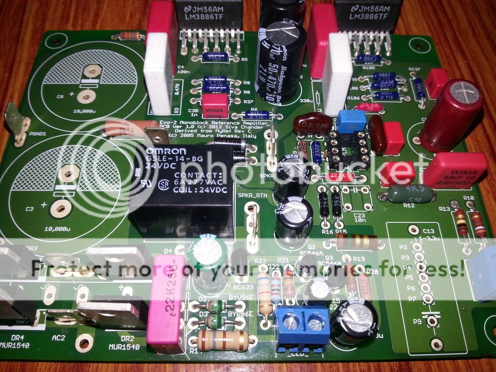
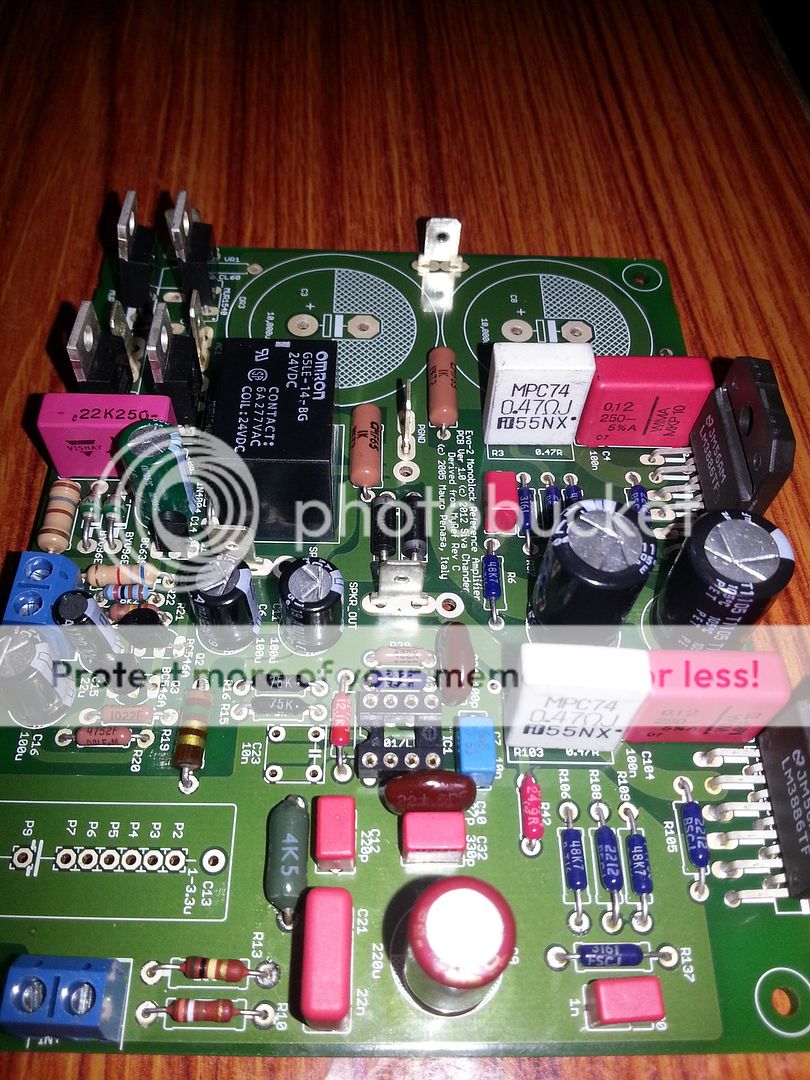
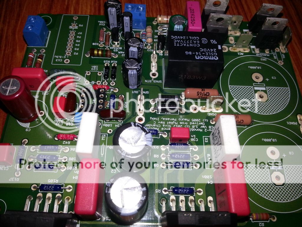
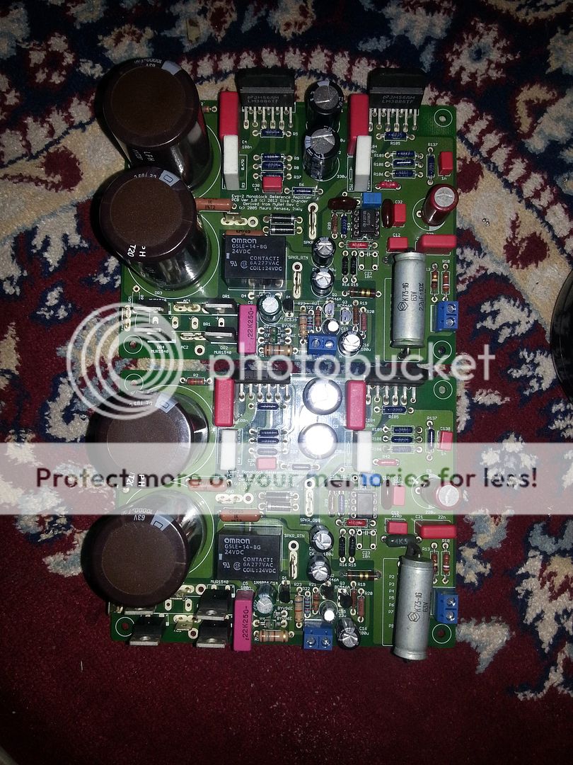
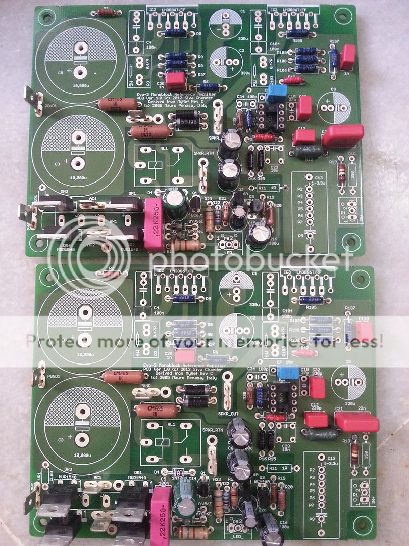
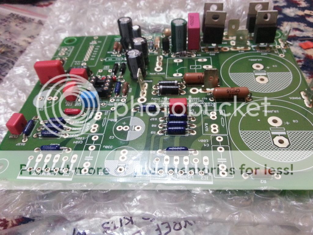
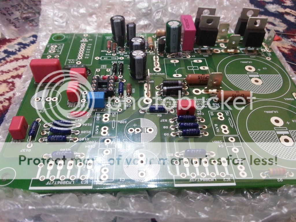
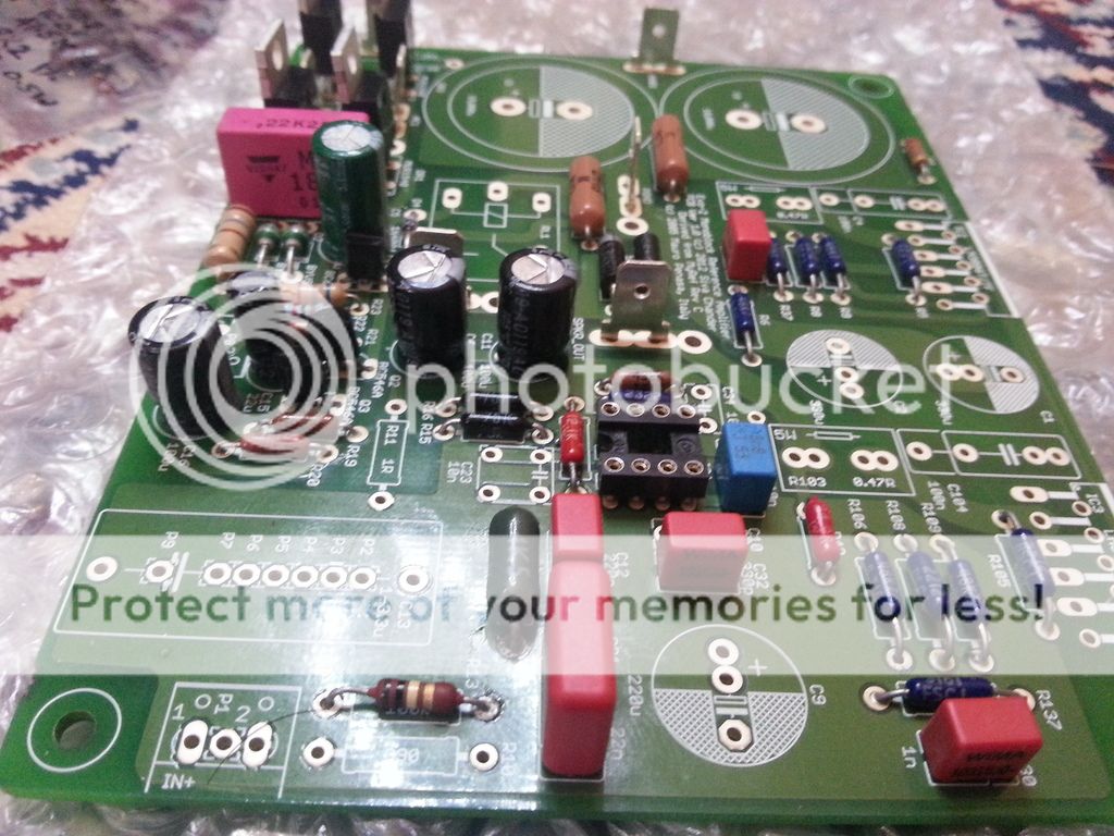
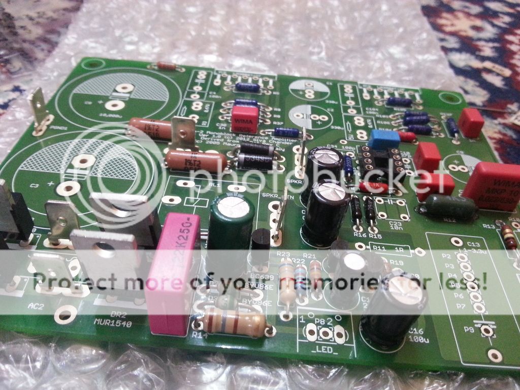
Partially populated boards, Please point out any mistakes so that I can correct them

20160320_160113_zpsfspeclip.jpg


20160320_160716_zpswttom1rb.jpg


20160320_160803_zpspqutkdf3.jpg


20160320_160830_zpsdokrpvna.jpg


20160320_160856_zpsgrdkznvv.jpg


20160320_160914_zpspvuvnsim.jpg


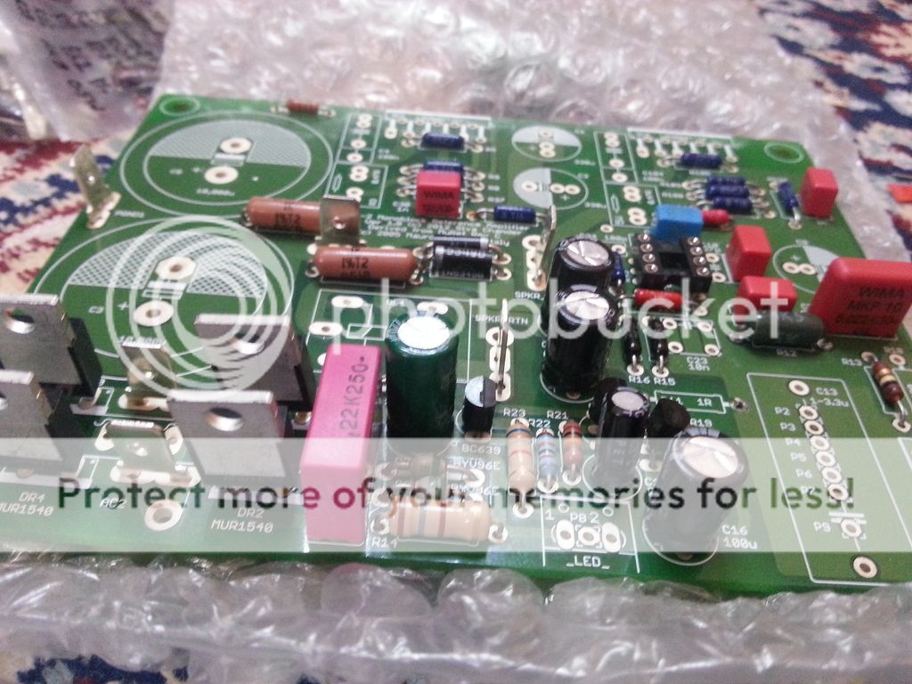
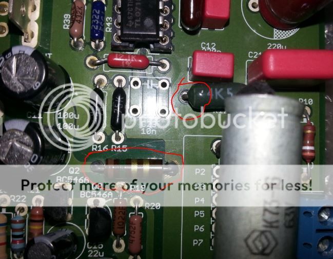
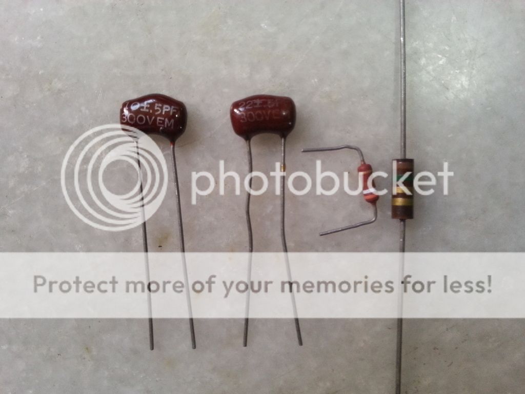
Components which I am not sure where I have to solder them, Linuxguru Could you please help me to identify which one from below image are R11, R10, C34 and C10.

20160320_154208_zpsnvypbnoi.jpg
 
Last edited:
Aves, looking good - no obvious error at first glance, but I'll take another more detailed look shortly. Please also re-check the polarities of all polarized components (diodes, zeners, electrolytics, opamp, transistors, etc.) before applying power.

The components shown are C34 (10 pF silver mica), C10 (22 pF silver mica), R10 (390E 1W Vishay/Philips MFR) and R11 (1.5E 0.5W Allen-Bradley Carbon Composition). The values shown correspond to Rev C compensation.

Let me know if any component is missing - only VR1 (CL60 thermistor) is omitted, IIRC. BR1, the integrated bridge rectifier is replaced by 4x MUR1540 to from the discrete bridge rectifier.

You can do initial tests with a DIP8 TL071 (should be easily available locally) before trying out the LF01 module at IC1. The polarity of the LF01 is such that Pin 1 is closest to the 2011 date as well as to Pin 1 of the SMD LM318 on it.
 
Last edited:
I forgot to mention that C23 is also substituted by C7. C23 may have physically interfered with the LF01 module, hence it's omitted and low-profile C7 is used instead to bypass IC1.
 
As far as I can see, everything looks good including the component polarities. You should be good to go for initial tests with TL071 at IC1 once you populate the caps. Visually inspect all solder joints again and reflow anything that looks dull or dry, if any. Look for solder bridges, shorts or breaks. Also clean any excess flux with IPA in due course.

For C3/C8, use 50V, 63V or higher rated caps if possible. In a pinch, non-standard 42V rated caps will also work, but they're less linear than the higher-voltage caps, other things being equal.
 
Thanks for the detailed look Linuxguru.

I bought 2 TL071 Opamps from the local market and completed soldering the Big Filter Caps (10000uf 63v Elna) and the input Cap.

I tried to test both the boards and I think something is seriously wrong with them.

I connected the power to 1st board and observed that both the LM3886 IC got instantly hot may be in 2 or 3 sec, I just disconnected it immediately before anything burns, but the I heard the relay sound (just one Click) and LED is steady state (Speaker protection looked working normally), I did not connected and audio in or Out.


Then I tested the 2nd board and Observed that IC's get gradually hot in some around 5 sec, but still it is not so hot as compared to the 1st board, I disconnected this board also within safe time and before burning the LM IC's.

I also tested without Opamps and observed same issue with both boards.

I did not see anything else getting hot other then the LM3886 IC's, I checked for any dry soldering joints but nothing seems to be wrong.


I have built LM3886 Amps earlier but in Idle state they do not become so hot, some time they may be just warm even when singing (Operational).

I am not sure where I did a mistake, I checked the polarities of the Caps and Diode which looks to be fine, also compared both the boards for errors in positions of each component.

Any pointer could help

20160325_192459_zpsrxiyh3eb.jpg


Regards
 
Last edited:
I Do not have a good Experiences in IC Amplifiers, I Just need to ask, Have you fitted the Heat Sinks with the IC's? May be this could be the reason.
 
Any pointer could help

Detailed email reply sent - start by using heatsinks even while testing, and check the rail voltages (chipamp as well as opamp) first. Aim to stabilize one board first, then copy all the fixes to the other board.
 
Last edited:
Thanks for pointers..

After further testing with my test Heatsinks found the 2nd Board is stable, I tested it with audio in and Speakers, it looks to work fine, did not observe any abnormal heating of chips, and I played one complete song in the test without any issues.

However the 1st board still have the heating issue from the 1st Second I connect the power, I am not able to dare to keep it on more then 5 Seconds even after connecting heatsinks, I also tried the troubleshooting by below mention steps.

"Check the soldering of C30 and C130 (1000 pF)"

"C34 can be increased to anything between 15 pF and 47 pF (say 22 pF). A ceramic cap should be OK. In a pinch, you can interchange C10 and C34" I tested with a 47pF Wima which I had available, but no luck in stabilizing the Chips.

"R42 can be removed and replaced with a jumper (0 ohms)"


What I am suspecting is, I did some mistakes while soldering this board.

1) While soldering R11, the PCB's track was damaged from the other side due to my over heating it (My fault), hence soldered the R11 from the front side, which is shown in the PIC (I have checked the correctness of the connectivity with the good board).

2) While pushing the Leads R12 through the PCB holes, the coating if the resistance chipped little, it is difficult to see if from above as it is just beside the left lead (Though I think this might not cause an issue but still wanted to know if it will make any difference)

Resis_zps04iaukhi.jpg
 
Last edited:
1) While soldering R11, the PCB's track was damaged from the other side due to my over heating it (My fault), hence soldered the R11 from the front side, which is shown in the PIC (I have checked the correctness of the connectivity with the good board).

2) While pushing the Leads R12 through the PCB holes, the coating if the resistance chipped little, it is difficult to see if from above as it is just beside the left lead (Though I think this might not cause an issue but still wanted to know if it will make any difference)

Resis_zps04iaukhi.jpg

If you fitted the resistor from opposite face, please check that the lead which was supposed to be in contact with the damaged part of the trace is in proper contact with the resistor even if you put resistor from opposite face of the PCB.

The slight chipping of the resistor coating should not matter at all.

If the chip amp is heating up immediately, i suspect it could be because some component has reverse polarity somewhere in the board. Take a circuit diagram, pencil in hand, then trace the full circuit, and tick off the connection of every polarised component, one by one. Trace from one end of the circuit board to the other end, and repeat just to be sure. Most likely it is a minor error. Or else, it could be a blown transistor or diode.
 
Yes, I checked the connectivity after I soldered it and also now after your suggestion, it looks fine.

I just measured voltages at LM3886 (31.2v) and at opamp (12v), I think it is fine.

One question I want to ask is, Does the amplifier work if something is wrong (will it sing), I just connected test speaker and observed that it seems to working. Any thoughts
 
Connected speaker and tested by playing music, no hum and music is clean but the LM3886 IC's stayed at 55C for some time then on 60C for some more time, after about 10 min it was about 66C, I unplugged to avoid any damage or reaching T-Max

Not sure why it is reaching so high temperature at a moderate volume (10-15%), are the IC oscillating (not sure if I am using correct terminology)
 
Last edited:
Yes, I checked it, it is around -10.2 mv.

Edit:
So, here is further update.

Some how amp automatically started stabilizing, I haven't changed anything, I just let it play for around 30 min, and the temperature reached till 65C and started dropping gradually even though Amp was playing.

Now the Temp is around 45.5C at idle still dropping further, and I am able to safely put my figure on the IC .

I am not sure if there is any logical explanation for this behavior of the AMP, but I am happy that it is stable now.

I will test if further and post updates.

Thank you Linuxguru, jls001 and sadik for the help.

Regards
Aves Bilal
 
Last edited by a moderator:
Thanks for pointers..

After further testing with my test Heatsinks found the 2nd Board is stable, I tested it with audio in and Speakers, it looks to work fine, did not observe any abnormal heating of chips, and I played one complete song in the test without any issues.
...
1) While soldering R11, the PCB's track was damaged from the other side due to my over heating it (My fault), hence soldered the R11 from the front side, which is shown in the PIC (I have checked the correctness of the connectivity with the good board).

2) While pushing the Leads R12 through the PCB holes, the coating if the resistance chipped little, it is difficult to see if from above as it is just beside the left lead (Though I think this might not cause an issue but still wanted to know if it will make any difference)

Hi Aves - Good to hear that one board is stable with the heatsink installed. On the other board, R12 is OK - the coating tends to flake off with age, etc. You can measure and check if it's within spec (4.5k). Regarding R11, you can check if the signal ground to PGND resistance measures the same as R11 (1.5 ohms) - you have to use the lowest multimeter resistance range to measure this. The exact value is not important, as long as it is around 1 to 1.5 ohms.

Also clean the solder side with IPA to check if there are any small solder bridges or shorts to the ground planes.

Edit: I have no clear explanation for how it stabilized after running for a while, but new electrolytics do take a while to run in (the oxide barrier has to form on the aluminium foils). However, it should not have a bearing on stability, since all the electrolytics are bypass caps or related to the speaker protection. The only exception is C9, the Elna Cerafine, which is in the feedback path. The other possibility is that one of the resistors drifted a bit and stabilized - R11 is one such candidate, since it's a carbon composition.

Anyway, enjoy your listening and keep me posted if the heat issues re-appear - I'll try to improve the stability margins in due course on my prototype board. For safety, you may want to stay with 8-ohm speaker loads until the stability issue is fully resolved. The DC offset values at ~ 10 mV are very good and there does not appear to be any issue there.
 
Last edited:
hello everybody
hello mr linuxguru, i am curious if u have these pcb s for sale.
the new Myref Evo-2 uses the same schematic as the My_Ref Fremen only in stereo?

please let me know, thanks
 
hello mr linuxguru, i am curious if u have these pcb s for sale.
the new Myref Evo-2 uses the same schematic as the My_Ref Fremen only in stereo?

PM sent. The Evo-2 is derived from the MyRef Rev C, but with dual current pumps in parallel at the output stage to double the current drive capability, thus allowing it to drive 4 ohm loads with twice the power rating (80W into 4 ohms) as the original MyRef (40W into 8 ohms).

The FE/Fremen Edition uses a different schematic and compensation values, but the FE compensation alone can be transplanted either to the MyRef Rev C or the Evo-2 if required.

The Evo-2 is still at the experimental/evaluation stage - only a total of 6 PCBs were fabricated, of which 4 are committed to prototypes, and the remaining 2 went to the OP of this thread who was willing to take the chance of building an amp which was still experimental.

If there's interest, I'll eventually run a respin of the Evo-2 including fixes (if any) that are found in the experimental phase. Meanwhile, I have kits and PCBs for the MyRef Rev C monoblock, and MiniRef v1.04 stereo board - both of which are lower power, but proven and validated designs.
 
I am also interested in the Evo 2. The my references rev c are singing well for the past few years but with the LM chip instead of the modded opamps LF01 which were showing sone instability.

My only problem was that my wharfedales have a nominal voltage of 6 ohms instead of 8 ohms and my toroidal transformer is rated 25 0 25 instead of 18 0 18 for lower impedance loads so l have some clipping at peak volumes although I hardly listen at those levels.
 
Check out our special offers on Stereo Package & Bundles for all budget types.
Back
Top