Hi Gurus,
Have come to you once again..............
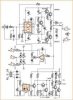
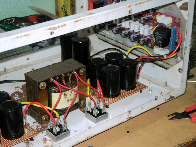
This time trying to build a power amp with LM49810 chip poised to deliver 200 watts each channel.
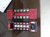
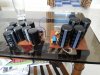
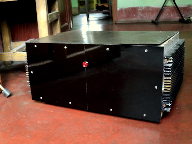
Bought the kits and made the heat sinks.
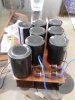
Just one issue - i have a 40-0-40 7.5 Amp traffo where as the circuit required +60 Volts, -60 Volts and +45 Volts & -45 Volts.
My friend FM Saheb has advised me to by another 30-0-30 Traffo.
Isn't there any other way? I don't want 2 traffos in same cabinet as i suspect too much emf .......
Can a simple volltage devider formula won't work?
Should i post the circuit diagram?
Later on, i shall be expecting your comments to improve the stock kit, but as of now need your inputs for getting it up and running.
And please also suggest which rectifier should i use....for the bridge. Should i put one polyster cap in parallel to each diode? I can make abridge unregulated, but do i need a regulated one. If yes, then will LM 78XX Series will do................?
Sorry - lots of questions this time !!
Thanks in advance.
Have come to you once again..............
This time trying to build a power amp with LM49810 chip poised to deliver 200 watts each channel.
Bought the kits and made the heat sinks.
Just one issue - i have a 40-0-40 7.5 Amp traffo where as the circuit required +60 Volts, -60 Volts and +45 Volts & -45 Volts.
My friend FM Saheb has advised me to by another 30-0-30 Traffo.
Isn't there any other way? I don't want 2 traffos in same cabinet as i suspect too much emf .......
Can a simple volltage devider formula won't work?
Should i post the circuit diagram?
Later on, i shall be expecting your comments to improve the stock kit, but as of now need your inputs for getting it up and running.
And please also suggest which rectifier should i use....for the bridge. Should i put one polyster cap in parallel to each diode? I can make abridge unregulated, but do i need a regulated one. If yes, then will LM 78XX Series will do................?
Sorry - lots of questions this time !!
Thanks in advance.