Soldering is fun!  :lol:hyeah:
Old Class-AB quassi-complementary for 2N3055
Pavel Macura's MOSFET Power Follower SE Class-A Source Follower
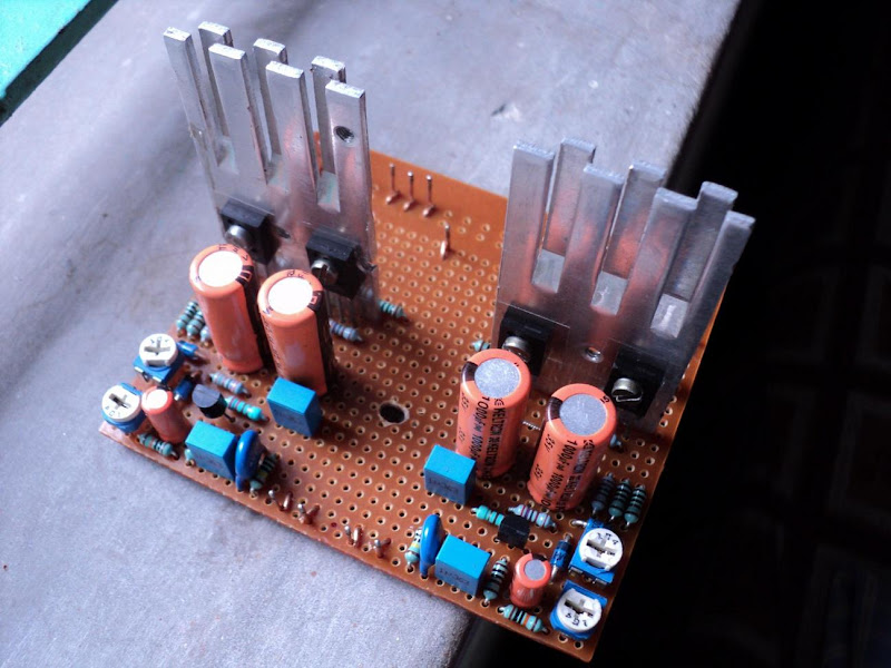
IRF540 Class-AB Little Monster(Excellent Bass)
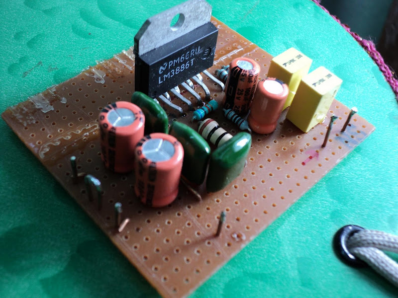
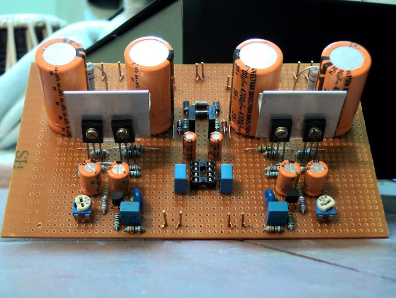
LM3886 Chipamp
Guitar Preamplifier with Diode Clipping distortion

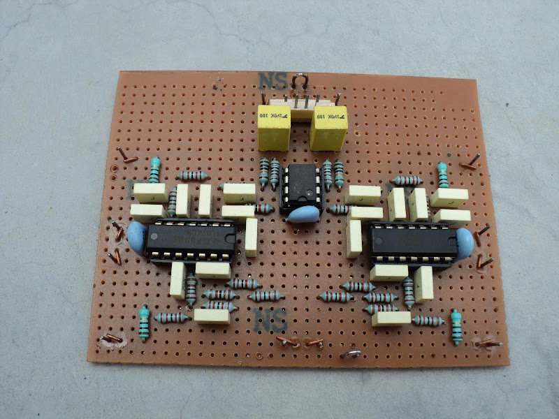
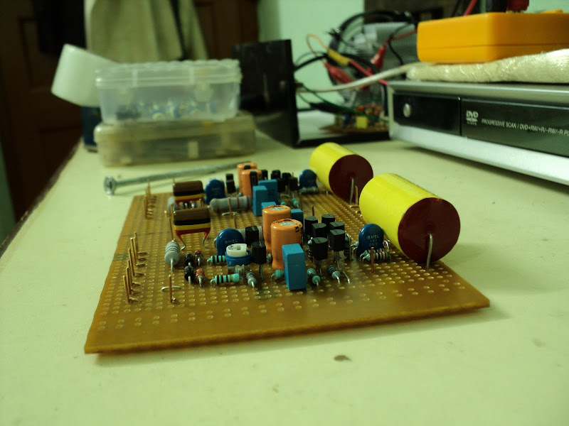
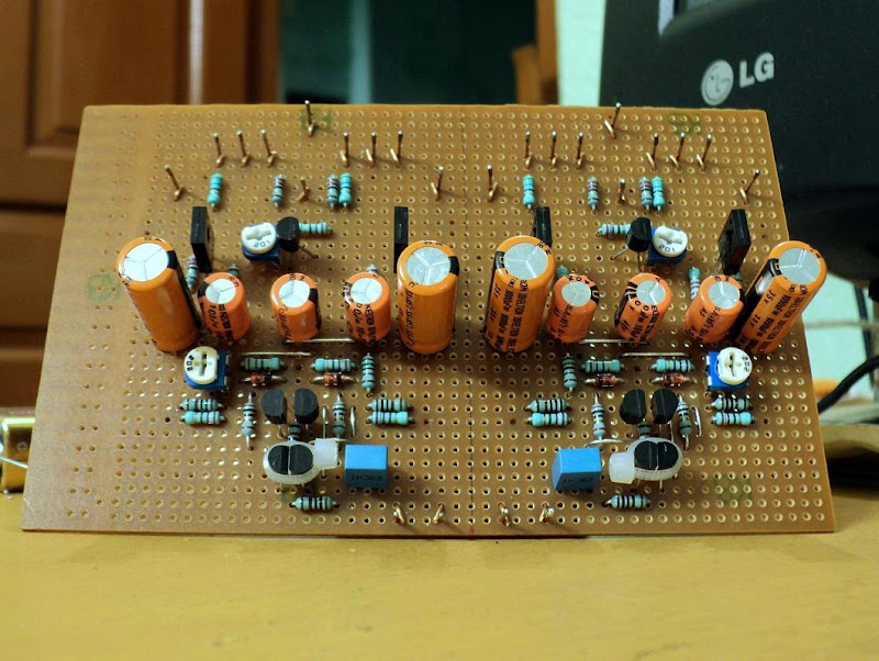
Linkwitz-Riley 24dB/octave active crossover
Finished old (and sold) Class-AB amp
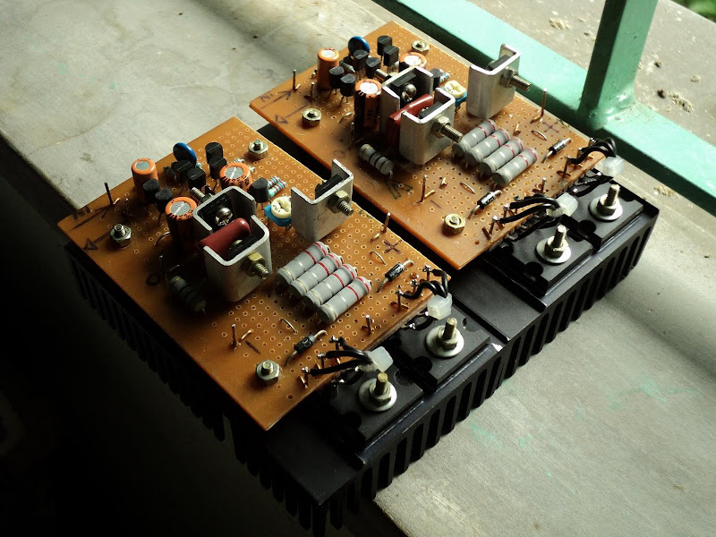
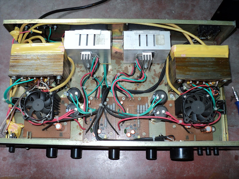
2SC5200 quassi-complementary Subwoofer Plate amps
Planning...

ESP P101 Clone(with guessed parts)
HEXFET input experimental SE Class-A amp(2 gain stage)
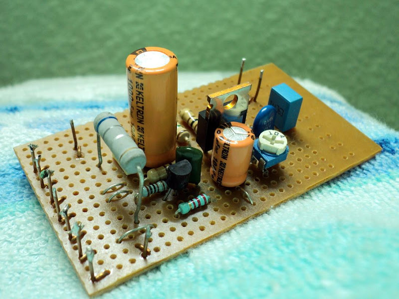
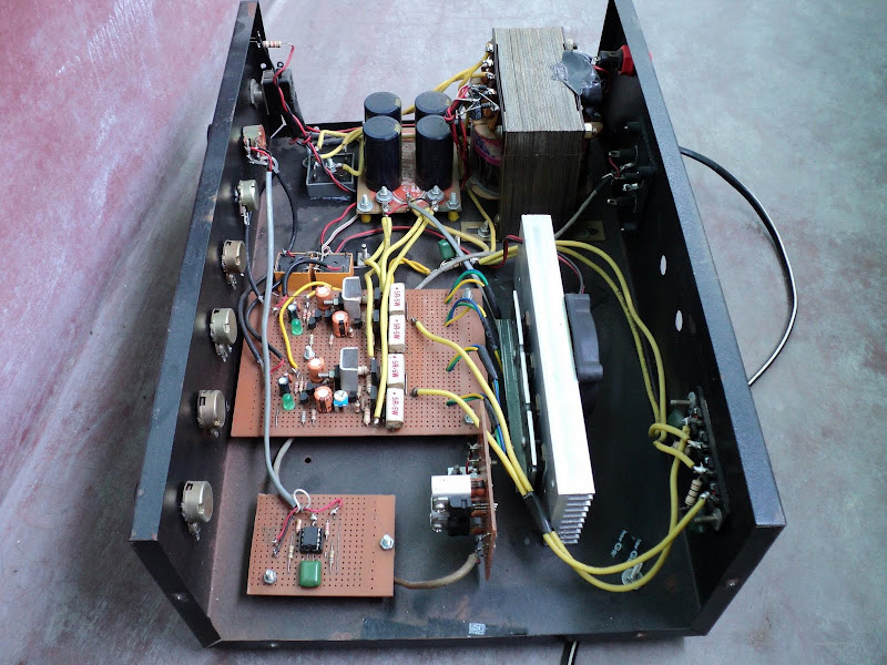
ESP Subwoofer Processor (Small but Magicalhyeah: )

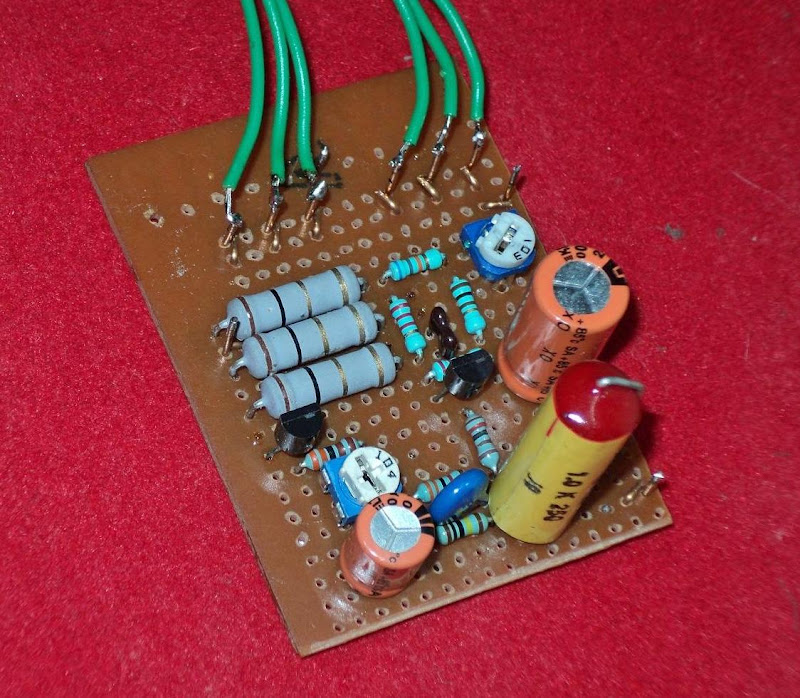
ESP Thermo-Fan controller

First finished stereo Class-A amp with Capacitance multiplier(sold)
Zen-type
SSA Failed Attempt
Micro DOZ
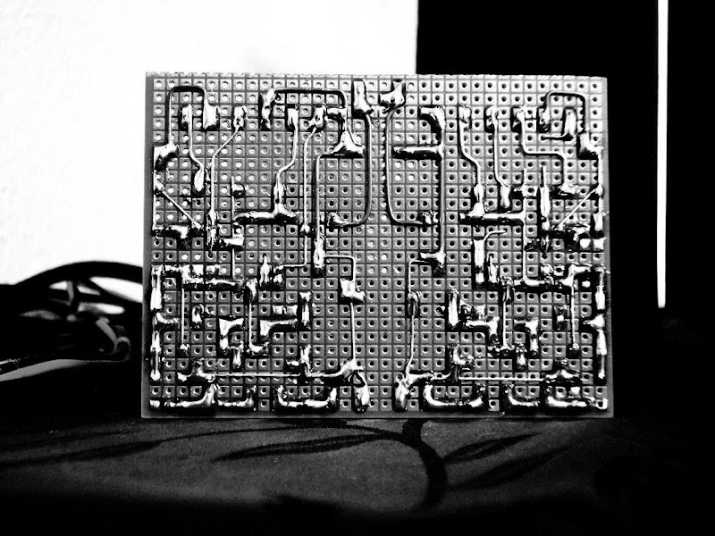
Micro DOZ underside
DOZ with DC Servo
DOZ with DC Servo underside
CMoy 2Watt Cutie Amp
shaan
:lol:hyeah:Old Class-AB quassi-complementary for 2N3055
Pavel Macura's MOSFET Power Follower SE Class-A Source Follower
IRF540 Class-AB Little Monster(Excellent Bass)
LM3886 Chipamp
Guitar Preamplifier with Diode Clipping distortion
Linkwitz-Riley 24dB/octave active crossover
Finished old (and sold) Class-AB amp
2SC5200 quassi-complementary Subwoofer Plate amps
Planning...
ESP P101 Clone(with guessed parts
)
HEXFET input experimental SE Class-A amp(2 gain stage)
ESP Subwoofer Processor (Small but Magical
hyeah: )
ESP Thermo-Fan controller
First finished stereo Class-A amp with Capacitance multiplier(sold)
Zen-type
SSA Failed Attempt
Micro DOZ
Micro DOZ underside
DOZ with DC Servo
DOZ with DC Servo underside
CMoy 2Watt Cutie Amp
shaan
Last edited: