amallalone
Member
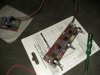
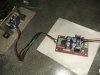
Recently I have brought 3 circuit from eight audio..one preamp module and one active subwoofer crossover and psu with crc filter..when I try to connect an 12-0-12v transformer to the psu and to the preamp or sub crossover the input or output passing dc current..the screwdriver tester confirms it..do I have grounding problem..
Whenever I tried to connect input or output from my pc the transformer stops passing any current at all..after removing the jack from input or output the transformer again started passing current..I tried 2 transformer..same result..
Whenever I tried to connect input or output from my pc the transformer stops passing any current at all..after removing the jack from input or output the transformer again started passing current..I tried 2 transformer..same result..