Dear All
Here are few phono Preamps which I built. (Pictures Below)
I used the circuit of Rod Elliott ESP phono circuit with National Semiconductors LM4562 op amps. A Sub Sonic Filter also added in the output of the phono stage. All resistors used are low tolerance metal film type and electrolytic capacitors are Keltron make.
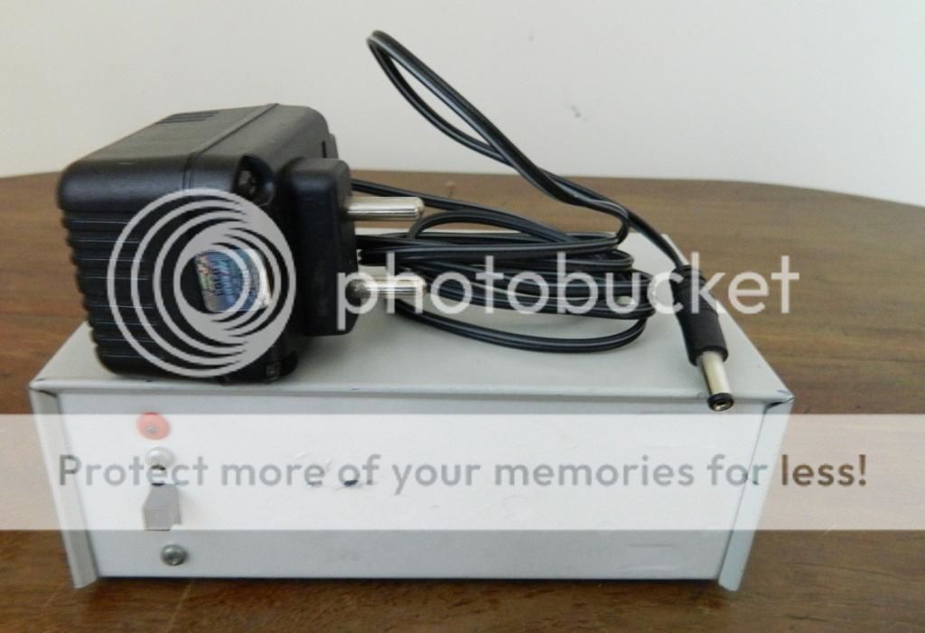
The power supply is 15V dual type and constructed with regulator chips LM337 and 317 instead of conventional 78xx, 79xx series. Supply filters are 2 nos 2200f and 4nos 1000f electrolytic capacitors. External 1A 16VAC wall adaptor used for feeding supply.
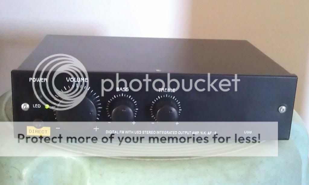
The cabinet is a small commercially available FM stereo metal box. For the front face plate I used two layer commercially available silver color sheet which is commonly using for vehicle nameplates / stickers. The unwanted holes in the cabinets are so hidden.
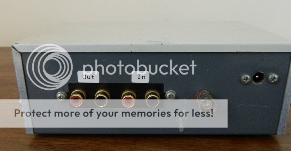
In other aspects high quality solder led and gold plated RCA sockets used. PCBs are Common Purpose type and resin coat done on layout side of PCB after completion soldering and testing. Shielded cables are used for all signal connection. Mirror image layout used for L&R channels for better sound balance and image.
Please note after burn in period the LM4562 ICs performance are not up to my satisfaction and after few trials with different op amps finally settled with Texas make NE5532.
Completed Final view
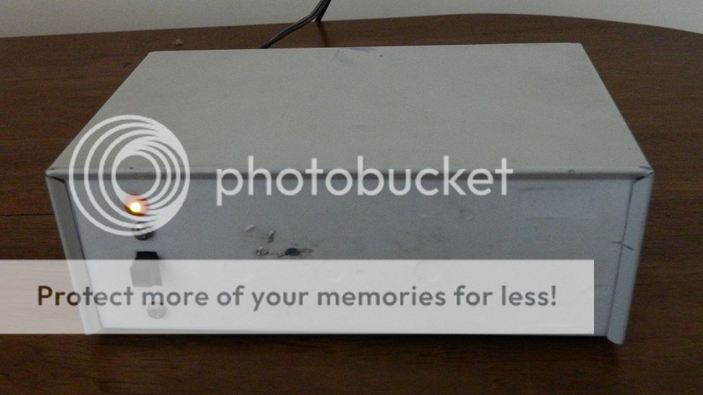
Front View while working
Rear View
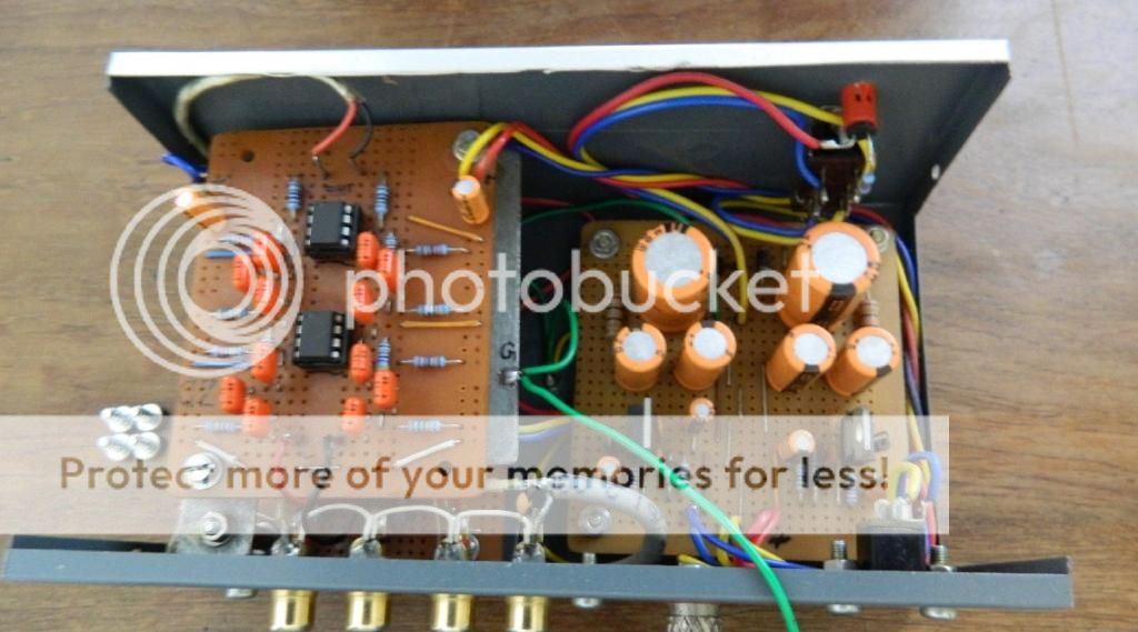
Inside View
The right side board is power supply board and left one is subsonic filter. The phono stage board is bottom of subsonic board.
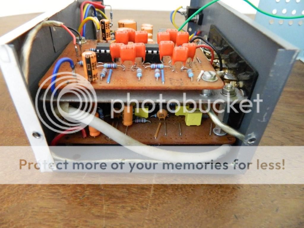
Side open view
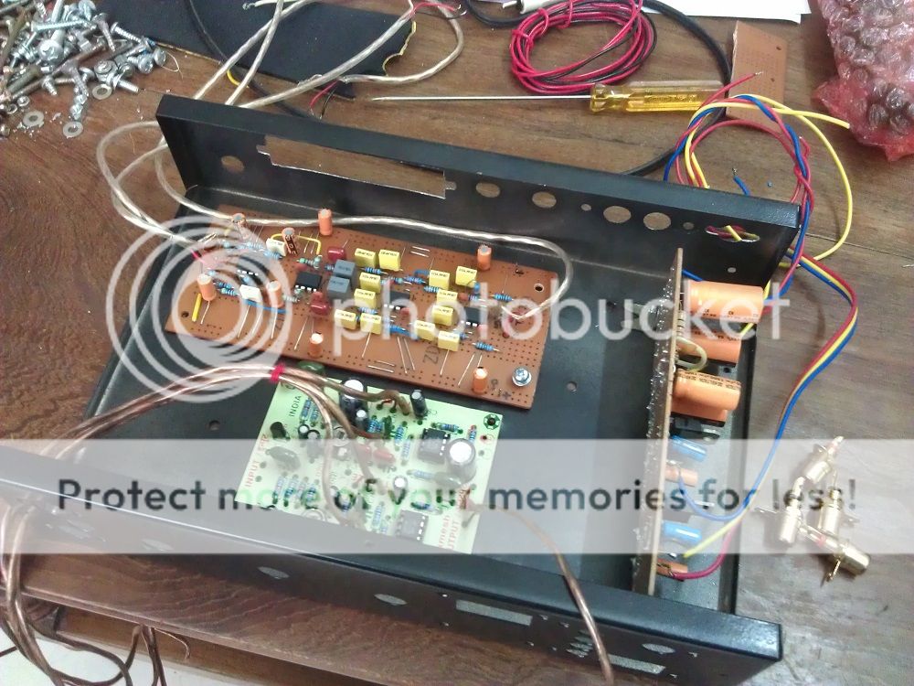
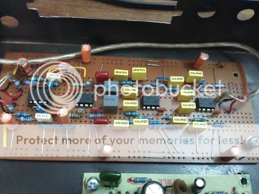
In the same way I constructed another phono stage for our FM Vijayan. In addition to the phono stage he asked Bass / Treble control also. I used a commercial bass/treble board for his purpose. A DIRECT switch provided for bypass the bass/ treble stage. The cost went up almost double due to the bass/treble board and dual control pots. Here the picture of that one.
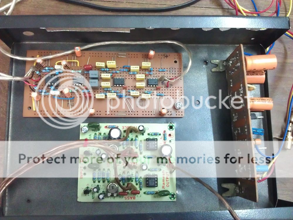
When assembling... The green board is the one for bass/treble. Power supply board mounted in vertical orientation. Phono amp and subsonic filter assembled as a single PCB.
The completed final view
Your views and comments are welcome.
Here are few phono Preamps which I built. (Pictures Below)
I used the circuit of Rod Elliott ESP phono circuit with National Semiconductors LM4562 op amps. A Sub Sonic Filter also added in the output of the phono stage. All resistors used are low tolerance metal film type and electrolytic capacitors are Keltron make.
The power supply is 15V dual type and constructed with regulator chips LM337 and 317 instead of conventional 78xx, 79xx series. Supply filters are 2 nos 2200f and 4nos 1000f electrolytic capacitors. External 1A 16VAC wall adaptor used for feeding supply.
The cabinet is a small commercially available FM stereo metal box. For the front face plate I used two layer commercially available silver color sheet which is commonly using for vehicle nameplates / stickers. The unwanted holes in the cabinets are so hidden.
In other aspects high quality solder led and gold plated RCA sockets used. PCBs are Common Purpose type and resin coat done on layout side of PCB after completion soldering and testing. Shielded cables are used for all signal connection. Mirror image layout used for L&R channels for better sound balance and image.
Please note after burn in period the LM4562 ICs performance are not up to my satisfaction and after few trials with different op amps finally settled with Texas make NE5532.
Completed Final view

Front View while working

Rear View

Inside View
The right side board is power supply board and left one is subsonic filter. The phono stage board is bottom of subsonic board.

Side open view

In the same way I constructed another phono stage for our FM Vijayan. In addition to the phono stage he asked Bass / Treble control also. I used a commercial bass/treble board for his purpose. A DIRECT switch provided for bypass the bass/ treble stage. The cost went up almost double due to the bass/treble board and dual control pots. Here the picture of that one.
When assembling... The green board is the one for bass/treble. Power supply board mounted in vertical orientation. Phono amp and subsonic filter assembled as a single PCB.


The completed final view

Your views and comments are welcome.
Last edited:
")