Help solicited in completing my amp....

subro99

Member
Joined
Aug 8, 2007
Messages
108
Points
18
Location
Kolkata
Dear Friends and Gurus,

Here i come to you again................

Long back in my school days i had ordered one pre-amplifier pcb and 2 channel power pcbs from visha electronics, mumbai.....

Those days i had to really struggle hard to buy resistors and capacitors from my pocket money and had assembled it partially.

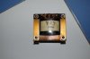
Going through the store room, i accidently bumped into these boards and all old memories started pouring in.........

Those fights with friends...:argue:.....and then buzoom friends again...:cheers:

And of course, the girl we used to dream and try our best to impress...those were the best bindaas days of one's life..........:yahoo::yahoo:

Then it struck me ---- why i am not completing this? But then i know nothing about tweaking this...but seriously, who cares...even those days, i used to solder and finally play small TBA810 amplifiers and it was so much fun...!!

So, guys - need to complete this for old times' sake at least and coming to all of you for support....

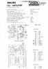
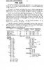
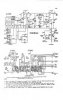
In my next post will post the schematics. Its an old very common PHILLIPS design with power transistors 2N3055.

By the way, Visha Electronics still exists in Lamington Road, Mumbai.
 
The black patches at the back of the PCBs are nothing but condensed soldering paste. The boards and the parts look absolutely ok.

And here is one 30-0-30 E-I Traffo..
 

Attachments

  • DSC_0242.jpg
    DSC_0242.jpg
    10.9 KB · Views: 132
Last edited:
The traffo is designed by one mr. pappu of Chandni Chowk. Its 5Aampere.

And here are the schematics.........

Do you guys think i should proceed........ or let past be buried in past?

Well, i sincerely would like to finish any unfinished work ( at least should have told that girl, that evry nite i died for her....!!) but then there are some...which if you wd have finished, meant life would have taken a different course altogether.
 

Attachments

  • page 1 001.jpg
    page 1 001.jpg
    10.9 KB · Views: 133
  • Preamp page 1 001.jpg
    Preamp page 1 001.jpg
    11.8 KB · Views: 132
  • Preamp page 2 001.jpg
    Preamp page 2 001.jpg
    11.8 KB · Views: 133
One thing bogging me down....!!

Those days there used to be input selector switches - to change source from phono, tape deck, radio etc.

Hence at the input end of the preamplifier, there are so many options which currently i dont need. Rather i need some tweaking at pre-amp input side so that overall some quality of sound could be improved...

Moreover, please guide me how to do impedence matching of the two...

Thanks in advance!!
 
As I can see it is a 15W amplifier (the schematic cannot be accessed properly, please upload a bigger image) and the design is very old, taken by the condition of the boards.

The output devices will need heatsink , and looking at the design there are better and bigger designs nowadays which are easier to build.

The components are old too and looks like should be replaced.

I suggest that you should start with a simple design like I did, a chipamp then get your hands with these.. these will be bulky.

And for supply options you will need rectifications and big caps like these....


images


EPCOS 10000uF/63V Capacitor
 
Phenolic boards, mostly CFRs, and some axial electrolytics - this has to be from the late-'70s or early '80s. I'll second the recommendation to dump it and build a new gainclone.

Some chicks were actually impressed by these kits then, huh? Somebody should have introduced them to me at that time.
 
Last edited:
It's never too late-or are you now over the hill?

>Some chicks were actually impressed by these kits then, huh? Somebody should have introduced them to me at that time.
 
Nowadays chicks don't dig Hi-fi , my Gf always criticizes me and tells me it's a waste of time and effort...

Hey, but who cares!!
They won't understand...


On topic :
I think the really simplistic approach of a gainclone is best for starting up..
 
Guys, are you motivating me or demotivating me?

Should i change the project or girl friend...er sorry, change my adherence to past...?:mad:

You guys are very interesting - you are making me hi-fi or my project low-fi just because it falls under senior citizen category?:cool:

As for Saheb, here you go, sweetie pie. See if you can dig something out of this....!!

 
Last edited:
Can you guys dump your old friend with whom you grew up that too when you relished the company. Point is, it is quite painful. I am not asking moon - if reasonably musical and clean sound is achieved, it would be of acceptable quality.

Thanks in advance.
 
Last edited:
Yes, it will work reasonably well if assembled correctly and the Vbe multiplier is biased optimally. It's a fairly minimal quasi-complementary design with bootstrapped VAS, similar to several commercial designs of that era. I had a Bevox BE5500 with a similar topology, but with AD149 germanium transistors and AC187/188 drivers. It sounded pretty good in its time, but had the tendency to blow the outputs if not biased accurately. The 2n3055 is more robust, and at 15W, there's not much danger of destroying them. However, you can consider upgrading to 2n3773 and higher rails, with some slight changes to biasing and resistors.

Edit: It has a somewhat clever/unusual dual-feedback path, due to the single-rail supply and output DC blocking capacitor. That capacitor is the weakest link, everything turns on its quality. Luckily, you can get good 2200 or 3300uF/50V capacitors these days for very little money.
 
Last edited:
I have made both these kits back in 1998. The preamp worked fine but the amp is still dead from day one. Possible the output semiconductors were fake or something didnt get much time with these after joining med school. Shifted to chipamps which were becoming better by each day.

It is really better to keep these framed for nostalgia sake like me and make a pass B1 preamplifier (Sachin & Omishra's group buy) and a LM3886 based amp (from linuxguru). Good quality components can be used because of low component count plus you dont need to do any biasing like the old discrete designs. It sounds better than my Rs. 50000 Yamaha RX675 Receiver.
 
Guys, are you motivating me or demotivating me?

Should i change the project or girl friend...er sorry, change my adherence to past...?:mad:

You guys are very interesting - you are making me hi-fi or my project low-fi just because it falls under senior citizen category?:cool:

As for Saheb, here you go, sweetie pie. See if you can dig something out of this....!!


Seriously, all of this components and just 15 watts?
 
I have made both these kits back in 1998. The preamp worked fine but the amp is still dead from day one. Possible the output semiconductors were fake or something didnt get much time with these after joining med school. Shifted to chipamps which were becoming better by each day.

It is really better to keep these framed for nostalgia sake like me and make a pass B1 preamplifier (Sachin & Omishra's group buy) and a LM3886 based amp (from linuxguru). Good quality components can be used because of low component count plus you dont need to do any biasing like the old discrete designs. It sounds better than my Rs. 50000 Yamaha RX675 Receiver.

I also own a chipamp and no preamp though.

@shubro99 : Im not discouraging you just that, there is more economical way of getting better quality and sound. If you dewlve into something your family members may expect something " toru " out of it and if they see this they will just discriminate you, well that's what happens to me I don't know about you , but still your choice, and there are members here who can help you both on any decision you make.


PS : I can help you make the supply though we can meet and get it going henceforth, it can be used in any decision you make...
 
Pickups?

A brain cell that has not been accessed for 45-50 years suggests that that is what we called turntable cartridges back then. Of course, given the era, turntable would have been the primary source --- so there is a phone stage in there? "Tape recorder" --- it's probably pre-cassette too.

I know nothing about the electronics or the build, but it looks like an antique for sources few people use any longer. Or can the experts here adjust it to modern-day line levels?
 
Last edited:
... Or can the experts here adjust it to modern-day line levels?

The preamp can be omitted, unless the builder has an turntable with a ceramic cartridge that can drive it.

However, the power stage is quite usable, with a full power sensitivity of about 1Vpp (~350 mVrms amplitude). A single volume control pot of about 10k to 22k to ground at the input is sufficient to scale the typical 2 Vrms line-level input to the lower level for the power amp.

A few changes to biasing the power amp make it usable with a +50V power supply, giving about +/- 22V swings into 8 ohms, or about 30W/ch RMS.

R16: 33 ohms/1W
R19: 22 ohms/1W
R1: 100k
R5: 82k

(The net effect of the above mods is to bias it closer to Class-B, to reduce the quiescent power as well as to make it operate well inside its SOAR curve, which also makes it more robust against accidental shorts on the loudspeaker terminals.)

The compensation shown is a heavy heavy-handed combination of slew-rate and bandwidth-limiting dominant-pole and Cherry slope-distortion compensation, which makes it very stable as shown, but at the cost of higher distortion (almost -50 dBr at 10W into 8 ohms, or ~0.3%, according to LTspice).

I played around a bit in LTspice, and found the following mods reduce distortion to a fairly competitive -70 dBr or 0.03% at 10W into 8 ohms, while still remaining stable:

C7: 15pF (silver mica or Philips Plate-Type P100 ceramic only)
C4, C6: 330pF (film/foil, e.g. Wima FKP2 or ERO KP1830)
C9: 150pF (film/foil, e.g. Wima FKP2 or ERO KP1830)

I'd also recommend using film caps at C1, C2 instead of electrolytics. Usable types/values are Panasonic ECQ-P 4.7uF/63V or in a pinch, Wima MKS2XL 3.3uF/50V (maybe 2 in parallel at each location).

C10 can be 1 or 2x 2200uF/50V Rubycon YXG or similar - it is a low-ESR type with good linearity (i.e. low tan delta).

It is also common practice these days to use larger caps to bypass the Vbe multiplier than the 10 nF shown for C8 - typical types/values used today are Sanyo Oscon, 10 or 22uF/16V.

No changes are required to any of the actives, though there are excellent Japanese low-noise small signal transistors which are usable at Q1: 2sa970 or 2sa992; and Q2: 2sc2240 or 2sc1845.

Don't even consider upgrading the NPN power outputs - this circuit is stable *only* with the slow as molasses 2n3055 as shown. Any faster output transistor is asking for trouble - 2sc5200 or 2n3773 are unstable in the simulations.
 
Last edited:
Join WhatsApp Channel to get HiFiMART.com Offers & Deals delivered to your smartphone!
Back
Top