12AX7 Cascode Tube RIAA stage, a re-design

drlowmu

Banned
Banned
Joined
Oct 28, 2020
Messages
721
Points
93
Location
Warrensburg, Missouri
Older, more experienced audiophiles I know tended to appreciate the Paragon 10, 12 / 12A, and E 12AX7 phono stages of the late 1970s. Trevor Lees made a similar circuit he cleverly adapted to a DYNA PAS 2 chassis. All of these Phono Preamplifiers used 12AX7s in a wide-band, high-gain cascode circuit arrangement. All of these models sounded good back then, and perform reasonably well in 2021.

I inserted a borrowed late-1970s Trevor Lees preamp into my reference ALTEC VOTT A7-8 horn system, only about two months ago, and certain aspects of its presentation blew me away - such as to it's uncanny sense of " aliveness " on a baritone voice, etc..

Reviewing the RIAA stage's schematic and parts employed, I just felt I had to build my own ( hopefully improved ) version of this same circuit, using modern upgraded parts and power supply techniques I know of in 2021, just to HEAR that result .

That is what this thread is all about.

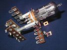
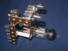
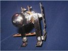
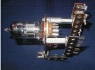
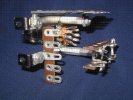
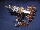
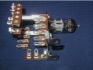
Pictured below is the " hardware " design / spacial relationship I just worked out this weekend, so as to be able to have short point-to-point wiring, and have a terminal to connect each part. It enables parts installation of the entire RIAA network and a very unique, custom power supply.

What is pictured individually feeds both triodes of a dual triode 12AX7 tube. Each triode will have it's own B+, double series SHUNTED ( to lower impedances ) and it will also individually employ two series L/C " Final Filter " B+ networks - ( a hash choke, film cap, a second hash choke, and film caps, plural ).

Imagine - a brute-force / passive quadruple filtered B+.

It in effect, the unique power supply arrangement separates each triode's B+ feed, from all the others. With this power supply arrangement, a film B+ capacitance supply is positioned within 1/4 of an inch ( or less ) of it's actual use-point, ..... intimate with each tube's Plate Resistor.

I will continue to post design details and build photos. I expect this build to take about three months.

Please note, most of the hardware parts ( shown below ) are manufactured in the USA by Keystone Electronics, and are readily available - such as their "board brackets ", 817 terminal strips, and hex spacers, ....... both in metal and white nylon.

Thank you for looking. These below - are multiple views of just one mechanism. This should be a fun and very rewarding DIY project.
Snip 1.JPG

Snip 4.JPG

Snip 5.JPG

Snip 6.JPG


Snip 8.JPG


Snip 9.JPG

Snip 7.JPG
 
Last edited:
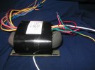
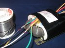
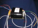
The cascode preamp's intended new Power Transformer arrived today - from China - in only two weeks travel time to the USA.

I measured it's DCRs, ( amazingly close where it matters ) and then test loaded it with Power Resistors, to document how much the transformer puts out under varying current draws. It is now documented, no load to full load, measured, recorded.

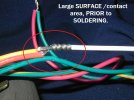
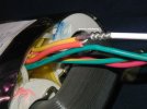
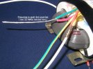
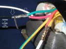
In less than 12 hours of ownership, I modified the Primary lead outs, and the High Voltage Secondary lead outs. Stock wire was 22 AWG, and I prefer larger wire, went to wide-band (silver content ) Mil Spec 14 and 16 AWG wire, in key spots. ( for Energy Transfer Efficiency ). m22759/11.

Photos are annotated.

drlowmu

001 edited.jpg002 edited.jpg003 edited.jpg009 edited.jpg010 edited.jpg013 edited.jpg014 edited.jpg
 
Last edited:
6-11-2021 PROGRESS report


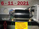
Mounted new phono stage's R-Core power transformer with all-brass hardware, into a 1961 era Test Equipment Donor Chassis today. I like it so far.

002 (2) snip edited 2.jpg


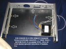
The " new" chassis' bottom plate ( below ) is heavy duty 14 gauge steel, and it is mounted to the chassis'frame, with a similar brass pyramid bolt mechanical technique.

004 (2) EDITED.jpg


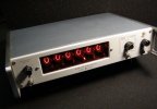
The " Donor " chassis ( below ) was a high class piece of test equipment in it's day !


5532A.JPG

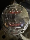
Wait until you see the vacuum tube B+ rectifier this phono preamp is going to get !
 
Last edited:
Do you have any preference for Not mounting tubes horizontally, for microphony ?
No, but that which you question should be a viable consideration. This I can deduce !

This is just a "proof of concept " build, to see how some unique power supply filtering ideas ( see below ) will perform VS a stock 1976 Trevor Lees cascode preamp I have on hand..

However, this phono preamp's tube rectifier certainly will be vertically mounted, due to it's particular filament and design.

HARP 3 of 3.jpg


I have been constantly experimenting with "double series shunting" of B+ nodes, and also "double series L/C ing " ( hash-chokes - L1/C1/L2/C2 ) of B+ nodes. This build will have both techniques applied, to discover what it does for a phono stage. My 6005 2021 new SE amp design is similar.
 
Last edited:
Thanks for your comments, drlowmu. I am sure that you are on your way to building a super sounding RIAA amplification stage. I have always had Great respect for Cascode Gain stages, in audio applications. I have had the pleasure to listen to the late Alen Wright's (Vacuum State) RTP3C pre amplifier, which used Cascode Amplification stages throughout, and also used Very tightly regulated Power Supplies, feeding the Glass Electronics

For years I have been following (pre) Valve amplifiers that have horizontally oriented the Valve, to create a slim design. In the early days, these stood out aesthetically, though there were murmurs of these products being more microphonic. Valve Microphony could be a significant issue in low level signal amplification, such as in an RIAA stage. I remain curious.

Your learnings and comments on this, once your build is complete, would be most welcome.
Thanks for your comments.

After your first post, I started to think a bit - about horizontal VS vertical. I think your comment is 100% valid. With you being the impetus, thanks, I decided ( prior to reading the above post ) to change the preamp ..............to all vertical orientated tubes. That IS the best way to do it !! I will just let the tubes stick out though holes I add to the top cover !! Thank you sir. No children or pets to worry about in my abode.

I would love to see a schematic on Allen Wright's RTP3C if you can send me one !!! I always paid attention to amps, not preamps, in past decades, so I am at a loss in knowledge.

This phono stage's B+ supply will not be actively "regulated". It will be " double series shunted" - a passive form of brute force B+ impedance control. On tube circuits I see, using active regulation, the stiff B+ supply circuitry is often distanced away from the tube, away from where the B+ is being used. Often several inches of wire away,.......... if you were lucky enough to have wire, and not a PC board !!

What I am curious to hear, is my own new intended execution.

After passively " double series shunting " a single B+ supply, out of eight triode sections in the Trevor Lees circuit, six will have their own " double series Final Filter ". These are combinations of carefully selected hash chokes and film caps, located right at the use point, of each triode. It's an L1/C1/L2/C2 passive filter, low in DCR, distanced perhaps 1/8th of an inch away from the tube's plate, or plate resistor.

So the film caps' energy storage ( several uF , of quality / selected multiple value film caps ) is positioned ON the circuit's use point - not several inches away, as we typically see in tube design. . Also, think about this, if 6 out of 8 tubes have such filters, this segregates the perturbations of the B+ from each " Final Filtered " tube, to the other tubes in the circuit. It is almost like having six separate supplies, on eight tubes.

I have never seen anyone in audio ever do this, except my audio mentor of the last 30 years. It is his idea. He says his Final Filters ( hash chokes and film caps ) made the biggest single MOD improvement, on preamps he has previously modified. I will try it now in 2021 !!

Another preamp design change has been decided by me in the two hours :

Besides the ( pictured previously above ) new R-Core power transformer, I will install a separate R-Core power transformer for my tube rectifier, rather than use the usual E-I core, etc. Besides a lower radiated field ( important in a phono preamp ), it will sound better due to the windings' equal resistance, capacitance, and inductance. Why not have it !! ??

I have thoughtfully worked-out all the precise electrical specifications today, for the transformer winder to meet. Well that's the latest. Thanks.

RTP3C ?

Jeff
 
Last edited:
Thanks for the very detailed info on how you "Double Series Filter" your power to the tubes. Sounds interesting and logical.

Clearly you shower your Valve audio builds with LOTS of TLC (Tender Loving Care) and the circuits respond with appropriate rewards.... The Best validation of a job well done.

I am sending you a personal message on the Alen Wright builds.

Do also google RTP3, there are reviews, since the Pre was also sold as a kit, commercially.

Cheers, Dinyar
 
MINI REPORT 6-29-2021

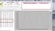
Recently ( 6-27 ), I used PSUD2 to design my own 350 VDC B+ supply. It uses a 300-0-300 Chinese R-Core received this month and measured under load, VAC and DCR wise. It will be split to each channel, after C2.

Rectifier will be over-speced, directly heated, a cool Russian " harp " filament 5C3S, similar to a 5U4G.

The low DCR ( 6 Ohms ) 2 HY choke is something custom made.

5 uF is the maximum suggested amount of capacitance, a 5C3S is rated for, with a Capacitor input filter.

All caps will be WIMA MKP4 and DC LINK film caps for the 350 VDC B+ supply. Double shunted passively at C3 and C4 ( 7.5 mA. at C3, and part of the 18 mA. at C4 ).

MK8s are vintage no-longer-made German Roderstein Resista resistors,............ absolutely lovely sounding resistors.

6-27-21  CASCODE  SAVE  USE PSUD edited.jpg

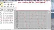
The 12 VDC filament supply ( below ) is for the four 12AX7s. It will nicely be a full Choke input filter, critical Inductance choke filter no less, ( Hammond 159ZA , off the shelf ) after a full wave bridge of low-noise Schottky rectifiers.

USE FILAMENTS `159ZA  6-27-21 edited.jpg

I have decided to use a larger 14 gauge all steel chassis, so as to not run out of space. Layout decisions need to be made before chassis punching ( Greenlee Punches and muscle ) , this coming week !! Fun to contemplate, how to arrange it all, what goes where ?

Jeff
 
Wharfedale Linton Heritage Speakers in Walnut finish at a Special Offer Price. BUY now before the price increase.
Back
Top