Another ACA build coming up

Subbu68

Well-Known Member
Joined
Mar 13, 2022
Messages
968
Points
93
Location
ABU DHABI, UAE
After a long search for my next DIY amp, settled on ACA thanks to FM @rajan, @sarathssca and @Kannan posts.

Gathered the good vibes about the amp and a pair of kits ordered on diyaudiostore, delivered to Abu Dhabi in 4 days flat. Planning to have them in bridged mono configuration.

We have 9 days off for Eid so a good way to spend time.

Some unboxing shots .. more to come as it progresses
 

Attachments

  • IMG_20220429_173454_hdr (1).jpg
    IMG_20220429_173454_hdr (1).jpg
    371.4 KB · Views: 59
  • IMG_20220429_173348_hdr.jpg
    IMG_20220429_173348_hdr.jpg
    355.3 KB · Views: 63
Last edited:
After a long search for my next DIY amp, settled on ACA

Congrats, I was thinking of getting them to India but the landing price was crazy!
Hope your country is better and it did not cost an arm or leg?
Can you share landing price if it is ok with you?

Waiting for your build and views on the sound.
 
I am also planning to get the 15W new kit but due to import cost I am holding up. However I am enjoying the 5W one
 
Congrats, I was thinking of getting them to India but the landing price was crazy!
Hope your country is better and it did not cost an arm or leg?
Can you share landing price if it is ok with you?

Waiting for your build and views on the sound.
The landed price is around $846 for the two kits. Yet to see the actual conversion to Dirham on my card account. It includes shipping and VAT plus duty of UAE . DHL may have charged a few dollars for the clearance service but no breakdown.
 

Attachments

  • Screenshot_20220429-195011.png
    Screenshot_20220429-195011.png
    394.2 KB · Views: 61
Further pics for one kit

The electronics, accessories plus board and complete kit

Waiting for a new soldering iron (Weller 30W with halo light) and solder (Stannol) from Amazon.ae to come in tomorrow.
 

Attachments

  • IMG_20220429_192036_hdr.jpg
    IMG_20220429_192036_hdr.jpg
    500.8 KB · Views: 63
  • IMG_20220429_192415_hdr.jpg
    IMG_20220429_192415_hdr.jpg
    487.9 KB · Views: 51
Work started. Was an excuse to get a new soldering iron and a mini soldering station for delicates.

Daughter chipped in to identify the resistors, stuff them and solder. Caps and small transistors complete. Chassis assembly, MOSFETS and wiring, finally testing.

Stuck the resistors with Washi tape prior to soldering so that they don't fall out when inverting the board - tape easily removable and no residue.
Board 1 -1 preps
Board 1-1 preps.jpg
Board 1-1 solder resistors
Board 1-1 solder.jpg
Board 1-2 preps
Board 1-2 prep.jpg
Board 1-2 solder
Board 1-2 solder.jpg
Boards 1 and 2 of set 1 done
Boards 1-1 2.jpg
 
Why do they supply ordinary wire even for input wiring? Shouldn't it be shielded?

My guess is it's because there is no a.c. supply inside to create interference.
 
Why do they supply ordinary wire even for input wiring? Shouldn't it be shielded?

My guess is it's because there is no a.c. supply inside to create interference.
Why not substitute with better cables, go with twisted wires. If available go with phoenix connectors or molex with input and output connections
 
Good job!
I hope you cleaned the board (both sides) post soldering with IPA and a stiff bristled brush or a tooth brush to clean all traces of carbon and flux.
Yeah, would do it. That bottle of IPA an ABB switchgear engineer gave me years ago will be of use now😃
If available go with phoenix connectors or molex with input and output connections
Recipe for upgrade 😉

Next iteration. Would the pinout match the PCB layout?
 
Why do they supply ordinary wire even for input wiring? Shouldn't it be shielded?

My guess is it's because there is no a.c. supply inside to create interference.
Abt the cables etc, they may not be the best, but what is included will work.
its a kit after all.

and yes, not having a PS inside is just another consideration.

for the power supply lines to the switch , the instruction is to doubleup on the red cable.
for sure its to save some costs in procurement of the cables for the kits.

steps 11 & 12

what I appreciated is, they have given these instructions, and its clear to enthusiasts that why its done this way.


nothing stopping us from upgrading any component/cable.

this is a great starting point. I havent made any upgrade (yet) followed the instructions, and it works great.
 
what I appreciated is, they have given these instructions, and its clear to enthusiasts that why its done this way.


nothing stopping us from upgrading any component/cable.

this is a great starting point. I havent made any upgrade (yet) followed the instructions, and it works great.
True,.it is a good kit with proper explanations in various guides and documents. Reminded me of my first radio kit from Jetking 😃.

Waiting for shops to open tomorrow to get some Molex or Phoenix connectors as suggested above by @Kannan so that the PCBs could be removed easily for any repairs.

Realised that Elekit have done this and it was so easy to disconnect, take out the boards and replace the caps last year when I upgraded it.
 
Progressing but slow. .

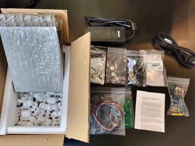
Chassis is a bit of a pain to assemble with screws from inside and all sides need to level. Slotted holes do help to level them. Fixed the top panel to keep the heatsinks level and adjusted the front and back panels and removed the top for wiring access.

In construction industry we say not to tighten the screws in one go..put in all structural members, keep screws a bit loose, level and then tighten screws diagonally one by one..that worked here.

It'd have been better with screws from outside connecting front panel and back panel to heatsink.Tapped in holes on the heatsink for front and back panels as well and top and bottom would have been better than the steel frames provided.

Next unit will have the top panel fitted first to both heatsinks and then the front and back panels.

Had fitted the PCBs on heatsink while soldering the MOSFETs. Did not want to dismantle so as not to disturb the devices. The output cap is coming in the way to tighten the front panel screws. IMG_20220504_142845_hdr.jpg
IMG_20220504_144944_hdr.jpg

Rear bottom row accessories done and wired.

@Kannan have put in Phoenix screw connectors for power and LED. Plugin type have different pitch so cannot go in. Molex not available locally.

Used salvaged speaker wires (from my old Jamo internal guts) for output wiring and main DC than what has been given in the kit.

LEDs wired with a piece from ribbon cable that was lying around. LEDs holes on front panel are way too big..had to shrink some sleeves around the LEDs to keep them from falling off. When doing a CNC work is it difficult to make the hole size to LED dimensions or all LEDs not of same size🙄🙄?

IMG_20220504_220435_hdr~3.jpg

DC to PCBs and input RCAs, XLR wiring balance. Hope to make it sing today.
 
Last edited:
Yeah, ACA Unit 1 has started to sing.

All wiring done and powered up with a set of 3 inchers salvaged from a Sangean Radio (WR-3). Wow... could not switch off.

Set the DC Balance at Q1 to 12V as per the build guide. Let it run in for little more than an hour. Measured the DC Balance again, it had gone down by about 0.15V. Not a significant drift I believe. Adjusted again to 12V. Closed up the chassis. Again a pain. The top cover one screw was mismatch with the hole of the frame. Had to loosen the heat sinks from rear and front covers and adjust again. This is the only issue I found irritating. Some shots below of internals of the completed unit.

It is driving Ahuja 12FRX OB beautifully in Stereo mode. Highs and mids are crisp. Bass is satisfying for though the sub would enhance it. Can live without it for our genre of music. Itching to complete ACA Unit 2.

DC Balance voltage after 1 hour of oepration

IMG_20220505_151728_hdr.jpg

DC Balance final adjustment
IMG_20220505_151639_hdr.jpg

Before closing the covers
IMG_20220505_154245.jpg

Any suggestions to make it neater inside? Or any upgrade suggestions?
 
I am trying to nitpick, lol.

Since you are not using shielded wires for signals, is is a good idea to route it so close to the circuit boards ?
I put them in the middle and hot glued them to chasis.

Also used hot glue to stick in the LED on the front panel, I think.

If you feel the main wire (to the power switch) will rattle, may some hot glue, or a 3m tape to secure it.

could you put the pic of the phoenix connector on the board ? its not visible from the pic.

are you driving it with elekit preamp now ?


on same speakers and source,
How does the sound compare to elekit power amp ?
initial impressions when its quiet at night ? (after the euphoria of the new amp wears out )
Thankyou for the tips Rajan

I didn't want to hot glue LED so that later taking out will not be an issue. With heatshrink sleeve they are relatively snug

I had thought of fixing the DC positive onto the cover but if again any repair or upgrade comes up it will be difficult to remove the cover. Maybe a cable harness would be better. I have reusable type. I will use that.

For the input wires i will try to get some shielded cables. I came across an article on shielding in audio that I have posted in the forum a couple of days back. Have to read liesurely and make the changes. Tried to minimise the length of wires.

With this length I can increase the clearance a bit more I think. Let me try. In power network works we are very particular to keep things straight and tidy, proper bends etc. 😉

Unit 1 was driven with iFi Audio IDSD Nano USB DAC and PC running iTunes. It was a kind of revelation.

Picture from Unit 2 below for connectors. Blackened one terminal to identify as -ve.
IMG_20220506_081140_hdr.jpg
 
Wharfedale Linton Heritage Speakers in Walnut finish at a Special Offer Price. BUY now before the price increase.
Back
Top