Attempting a passive DAC

Hari Iyer

Well-Known Member
Joined
Feb 8, 2010
Messages
3,837
Points
113
Location
Mumbai
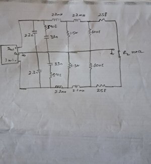
After using an audio transformer coupled based passive DAC for the LPF, i shall now be attempting a passive DAC based on using just resistors, inductors and capacitors. Nothing complex, but just a simple Butterworth based filter. There are two poles in series coupled back-to-back for allowing roll-off at 44Khz and 108Khz. I am not sure how much attenuation they would provide as i am still learning to use the LTspice simulator. Below is the simple schematic,
1701921280214.jpeg

Not sure if anyone in the forum have tried this before. If yes, need suggestions / inputs. Thanks.
 
Last edited:
After using an audio transformer coupled based passive DAC for the LPF, i shall now be attempting a passive DAC based on using just resistors, inductors and capacitors. Nothing complex, but just a simple Butterworth based filter. There are two poles in series coupled back-to-back for allowing roll-off at 44Khz and 108Khz. I am not sure how much attenuation they would provide as i am still learning to use the LTspice simulator. Below is the simple schematic,
View attachment 81759

Not sure if anyone in the forum have tried this before. If yes, need suggestions / inputs. Thanks.
How do you feed the digital signal to this ? Did you mean an analog filter here?
 
How do you feed the digital signal to this ? Did you mean an analog filter here?
I will be feeding the signal after the DAC chip, the Iout+ and Iout- signal after the DAC chip will be fed. This is a passive LPF without any op-amps or discrete transistor or tubes. There is a growing trend of DIYers doing this past 15 years as there are some issues with the active implmentation. Transformer implementation is good, but the cost of the audio transformer does not justify DIY attempt.

i have today ordered the components for this built and will do a P2P wiring as there are just few components.
The title of your post is misleading ;)
 
The title of your post is misleading ;)
Ok. So what should be the title for this post? Any modification is only after DAC chip, wether if it is passive LPF, Active LPF, Transformer or R2R. So any person with average technical understanding of DAC should be able to understand that imo. This post not for non- technical person.
 
I had actually built the LPF as per post #1 last week. Though there was good rolloff from the filter, the output gain was very low. As it was an excel based design without any simulation etc, I was not expecting it to work ok in the first attempt. In the meanwhile, I downloaded LT Spice simulator and took 4 days to learn using the simulator. Today finally, I could modify some values and get a decent LPF simulation that agrees with the PCM1795 datasheet. Tomorrow shall try hooking it up with the new design values and check once again and report.

Thanks for looking.
 
Ok. So what should be the title for this post? Any modification is only after DAC chip, wether if it is passive LPF, Active LPF, Transformer or R2R. So any person with average technical understanding of DAC should be able to understand that imo. This post not for non- technical person.

R2R is the DAC chip itself, not post DAC processing like transformer or passive or active Current to Voltage (I/V) conversion.

For all passive I/V conversions, the very limited current output capability at the I/V node must be very carefully factored in, otherwise you will get far more distortion from the passive IV conversion then if you used any active conversion.

Feeding such large capacitors, inductors & resistors from the miniscule current available at the I/V node seems ambitious to me.....
 
I was wondering exactly the same thing that @IndianEars is talking about. The current output of a single DAC chip is very low and this needs to be converted to at least a 2v output either by passive or active means.

Are you planning to stack chips to increase the current output? That is the common method used in most of the passive resistor ladder based output stages.
 
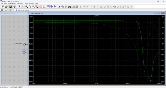
I am able to get 0dB in my simulation till 17.5khz and -9dB at 22.05khz and -17dB at 26khz. At 44.1khz it's-35dB. The source resistor is 820 ohms which is my DAC output impedance and the load is 10kohms. Infact the 2.2mH was not enough for rollofff and I Ned atleast 10mh for a decent steep rolloff. Still working on the simulations when I type this.
 
I am able to get 0dB in my simulation till 17.5khz and -9dB at 22.05khz and -17dB at 26khz. At 44.1khz it's-35dB. The source resistor is 820 ohms which is my DAC output impedance and the load is 10kohms. Infact the 2.2mH was not enough for rollofff and I Ned atleast 10mh for a decent steep rolloff. Still working on the simulations when I type this.
Something very wrong in your calculation of the effective load as 10K Ohms.

I am referring to the circuit sketch you have posted on 7th Dec.

All Calculations @ 20,000 Khz

The 2.2 nF cap itself presents 3K6 ohms

The 390 Ohms + 33nF = 731 Ohms

The combination of these 2 alone is a Very low impedance of 607 Ohms... ie MUCH below 10 K Ohms.

the 2.2 mH presents an impedance of 276 Ohms feeding 1K5 = 1,776 Ohms. This applied across 607 Ohms will result in 470 Ohms ... which is more than 20 Times lower than your expected 10 K Ohms.

The remaining components will lower this 470 Ohms even further.....
 
The 390 Ohms + 33nF = 731 Ohms
This is 631 ohms

The combination of these 2 alone is a Very low impedance of 607 Ohms..
This is 536 ohms

This applied across 607 Ohms will result in 470 Ohms

This is 408 ohms
The remaining components will lower this 470 Ohms even further.....
Most components values are now modified. This is still under design stage, not completed. Shall post final schematic once completed. Thanks for your effort in calculating values.
 
Last edited:
Hari, I think you have missed my point COMPLETELY.

The specific values serve only an indicative purpose... Your modified circuit has even lower Impedance (Load on the DAC's I/V node).

There is No way the DAC will be able to drive these low impedances, without gross distress.
 
Finalized the LPF and the FR response is as below,

1702803857627.png

Avoiding schematic to prevent analysis parlance.
 
Avoiding comment in the absence of info.

Also seems comments or feedback is not welcome on this thread, .....

so Hari, can you please clarify the purpose of this thread?
 
Last edited:
Avoiding comment in the absence of info.

Also seems comments or feedback is not welcome on this thread, .....

so Hari, can you please clarify the purpose of this thread?
I want to built and then confirm the schematic. Your theoretical analysis is not helping me withvany modification and prevents me to freely design. Hence shall built, listen and then confirm the schematic.
 
Wharfedale Linton Heritage Speakers in Walnut finish at a Special Offer Price. BUY now before the price increase.
Back
Top