Buzzing noise from Philips 533 Turntable

Joined
May 22, 2022
Messages
8
Points
1
Location
India
Hello all,

I am facing a problem with my Philips 533 turntable very often. When I turn on the turntable, it gives a solid buzzing sound for a few seconds with the power indicator light dimming, then everything becomes ok. Also, sometimes it gives the buzzing sound in the middle of playing a record & the power light starts dimming. Then everything becomes fine again after a few seconds.

I have checked the audio cable & speakers they are completely ok. I have also tried changing the speaker with a different cable. Can anyone please provide a proper solution to it & can explain to me why this is happening?

Kind Regards.
 
Just change capacitors inside your vintage amplifier present inside 533 turntable. Actulally you must change all capacitors to regain its original sound when it was new. Or you can start rebuilding one by one by changing power supply and power filter capacitors. It might solve your problem.
 
Just change capacitors inside your vintage amplifier present inside 533 turntable. Actulally you must change all capacitors to regain its original sound when it was new. Or you can start rebuilding one by one by changing power supply and power filter capacitors. It might solve your problem.

Thank you for the suggestion. Can you please name the capacitors which I need to change? I will go to the market & buy them. By the way, do I need to change the transistors also?
 
Hello all,

I am facing a problem with my Philips 533 turntable very often. When I turn on the turntable, it gives a solid buzzing sound for a few seconds with the power indicator light dimming, then everything becomes ok. Also, sometimes it gives the buzzing sound in the middle of playing a record & the power light starts dimming. Then everything becomes fine again after a few seconds.

I have checked the audio cable & speakers they are completely ok. I have also tried changing the speaker with a different cable. Can anyone please provide a proper solution to it & can explain to me why this is happening?

Kind Regards.
Sounds like a power switch issue indeed. The buzzing sound with the dimming and flickering power light indicates sparking inside the switch. Can be resolved by carefully opening the switch and by cleaning up all the contacts with wd40.
 
I recently joined the forum.
I am looking for circuit diagram of Philips 533 Turntable, specially the Motor speed governor circuitry,
Can any body help me with it.
Thnks in advance,
 
w
Attaching the PDF scan. Hope it serve your purpose.
What a lovely little circuit around AC187/AC188 output transistors. Back in those times, Philips small-amplifier designs for portable gear like record players, cassette recorders, radio-cassette recorders and transistor radios, were the best-sounding ones.
 
w

What a lovely little circuit around AC187/AC188 output transistors. Back in those times, Philips small-amplifier designs for portable gear like record players, cassette recorders, radio-cassette recorders and transistor radios, were the best-sounding ones.
Hi
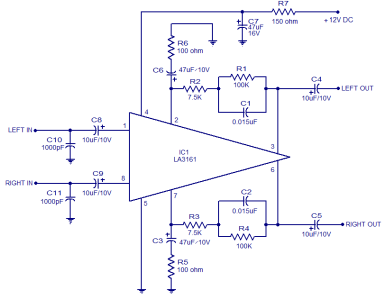
For Interest of others, as i was not able to obtain old vintage transistors , i built a preamp with LA3161 IC. And it matched beautifully with the Ceramic Cartridge. Gives sound as original.
Can be helpful for somebody who is having trouble matching the Impedance of Ceramic to a Solid state Amplifier.
Thnks
 
Actually the later models of these Philips record players moved from the Germanium AC187/188 based designs to TBA810 IC based designs. It would be nice if you can share the circuit of the LA3161 preamp.
 
Actually the later models of these Philips record players moved from the Germanium AC187/188 based designs to TBA810 IC based designs. It would be nice if you can share the circuit of the LA3161 preamp.
Attached. Worked perfectly for me. Can use it in mono or stereo option .
 

Attachments

  • LA3161-stereo-preamplifier-circuit.png
    LA3161-stereo-preamplifier-circuit.png
    28.5 KB · Views: 14
Hi
While restoring the Philips 533, i was able to restore the audio part BUT the speed governor has a problem of high speed.
I measured the speeds , instead of 45 rpm it is almost 87 rpm, similarly for 78 rpm it is quite high.
Have already changed the Transistors.
Not able to trace why speed is more. The adjustable resistance for biasing the transistor hardly affects the speed as in any case it will be for minor speed corrections.
Any idea where the problem may be in the circuit. All resistances in the circuit are again measured to be correct.
Waiting for suggestions.
Thnks
Caution: being a germanium design, the ground of the circuit is the (+) rail of the power supply and battery. The power supply diodes and in-circuit semiconductors (including diodes) are wired keeping this aspect in mind. The polarity of electrolytic capacitors will also appear to be in the opposite direction due to this (very important to note this if any recapping exercise is undertaken). Also, the simple logic is, if a motor is racing, it is being offered a higher voltage than it is supposed to receive under normal circumstances. This can cause the motor to heat up and if it does not burn out and fail, the associated wear may be higher causing a decline in performance and/or lifespan.

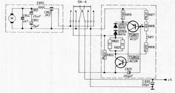
Many years ago, during my school days, my father gave me an old Philips Radiorecorder (radio cassette recorder) 22RR482 which had the same issue - it was running super-fast, music sounded like the chipmunks. I recollect checking the transistors and they were ok, my father suggested that we should change the diodes (I don't recall what value we used as substitutes or whether they were schottky or signal diodes), we also changed R822 (820E) as I recollect it was showing 50 ohms or something when my father took it out of the circuit and tested it (resistors tested while in circuit may exhibit incorrect readings). It slowed down significantly but there was heavy motor noise coming through the speaker and also it was still running faster than normal. I recollect he changed the zener diode in the power supply section and then the speed issue was resolved. The motor also exhibited good torque for rewind and fastforward. The speed adjustment preset was also working normally, could increase and decrease the speed significantly. The motor noise issue was resolved by changing capacitor C630, 330mfd.

Philips 22RR482.png

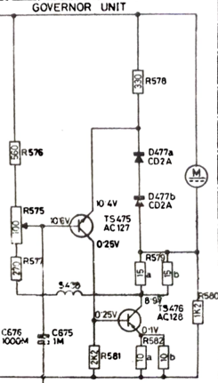
Looking at the governor circuit of the 533, the design is actually similar:

533.png
Assuming you have replaced the AC127 and AC128 with a similar metal cap germanium pair, I would suggest that you retest them (continuity/diode setting on the multimeter) outside of the circuit. You should not get any voltage flow from collector to emitter and vice versa as if you do, the transistor may be leaky. Even un-used germaniums may turn leaky while in storage. Also check the CD2A diodes and resistor R580 (1.2K) as if this resistor's value drops, the motor will speed up. That little choke (coil) should also be checked. It should not be open or shorted). Also check the capacitance of C675 1mfd, especially the polarity (this is a germanium circuit and the (+) rail is ground. Also run voltage checks across the collector, emitter and base of both transistors and you should get readings very close to what is mentioned in the circuit diagram. The next check would be to measure the voltage across the power rails (across the 1000mfd filter capacitor and compare the voltage across the motor. This is a 12v circuit when operated via AC mains and 9v circuit when operating on batteries. I recollect my Philips radio recorder worked on 9 volts when powered via AC mains, and on 7.5 volts when batteries were used. The cassette recorder featured a 5v motor and the speed controller circuit provided it with 5 volts irrespective of whether 9v or 7.5v came from the power supply. So coming to your 533, if you check the voltages across the motor, it definitely should not be 12v and you should get reduced or increased readings when you turn the preset. I suspect your record player has a 6v or 5v motor. Its a simple circuit and should definitely be able to get it to work.
 
Last edited:
Caution: being a germanium design, the ground of the circuit is the (+) rail of the power supply and battery. The power supply diodes and in-circuit semiconductors (including diodes) are wired keeping this aspect in mind. The polarity of electrolytic capacitors will also appear to be in the opposite direction due to this (very important to note this if any recapping exercise is undertaken). Also, the simple logic is, if a motor is racing, it is being offered a higher voltage than it is supposed to receive under normal circumstances. This can cause the motor to heat up and if it does not burn out and fail, the associated wear may be higher causing a decline in performance and/or lifespan.

Many years ago, during my school days, my father gave me an old Philips Radiorecorder (radio cassette recorder) 22RR482 which had the same issue - it was running super-fast, music sounded like the chipmunks. I recollect checking the transistors and they were ok, my father suggested that we should change the diodes (I don't recall what value we used as substitutes or whether they were schottky or signal diodes), we also changed R822 (820E) as I recollect it was showing 50 ohms or something when my father took it out of the circuit and tested it (resistors tested while in circuit may exhibit incorrect readings). It slowed down significantly but there was heavy motor noise coming through the speaker and also it was still running faster than normal. I recollect he changed the zener diode in the power supply section and then the speed issue was resolved. The motor also exhibited good torque for rewind and fastforward. The speed adjustment preset was also working normally, could increase and decrease the speed significantly. The motor noise issue was resolved by changing capacitor C630, 330mfd.

View attachment 76914

Looking at the governor circuit of the 533, the design is actually similar:

View attachment 76915
Assuming you have replaced the AC127 and AC128 with a similar metal cap germanium pair, I would suggest that you retest them (continuity/diode setting on the multimeter) outside of the circuit. You should not get any voltage flow from collector to emitter and vice versa as if you do, the transistor may be leaky. Even un-used germaniums may turn leaky while in storage. Also check the CD2A diodes and resistor R580 (1.2K) as if this resistor's value drops, the motor will speed up. That little choke (coil) should also be checked. It should not be open or shorted). Also check the capacitance of C675 1mfd, especially the polarity (this is a germanium circuit and the (+) rail is ground. Also run voltage checks across the collector, emitter and base of both transistors and you should get readings very close to what is mentioned in the circuit diagram. The next check would be to measure the voltage across the power rails (across the 1000mfd filter capacitor and compare the voltage across the motor. This is a 12v circuit when operated via AC mains and 9v circuit when operating on batteries. I recollect my Philips radio recorder worked on 9 volts when powered via AC mains, and on 7.5 volts when batteries were used. The cassette recorder featured a 5v motor and the speed controller circuit provided it with 5 volts irrespective of whether 9v or 7.5v came from the power supply. So coming to your 533, if you check the voltages across the motor, it definitely should not be 12v and you should get reduced or increased readings when you turn the preset. I suspect your record player has a 6v or 5v motor. Its a simple circuit and should definitely be able to get it to work.
Thanks for the suggestions. Had tried almost all these in order to reduce the voltage across the motor.
May be the Ac128 has a leak between C to E, that is why the drop across it is insignificant.
I will try all these options again, specially changing the Ac 128.
 
Thanks for the suggestions. Had tried almost all these in order to reduce the voltage across the motor.
May be the Ac128 has a leak between C to E, that is why the drop across it is insignificant.
I will try all these options again, specially changing the Ac 128.
if germanium transistors are not available, a more modern variable voltage circuit using a regulator IC would be an easy substitute (all this is assuming the motor is in good order)
 
if germanium transistors are not available, a more modern variable voltage circuit using a regulator IC would be an easy substitute (all this is assuming the motor is in good order)
Hi
I changed the Preset resistance and was able to get the Motor working . However even after lots of adjustments to the Preset resistance and also adding/deleting more resistance, the speed at 45rpm is ok but at 33 rpm the motor does not take load once the Arm is placed on the record. At 78 rpm setting the speed is more ( around 85) , at 45 it is ok and at 33 rpm speed drops down to 14 rpm on load.
So i am planning to put external IC Voltage regulator to feed the motor. Any idea what will be correct voltage for philips 533 motor ? Must be less then 9 v ( as battery itself is 9v ) . Pl advise.
Thnks
 
Get the Award Winning Diamond 12.3 Floorstanding Speakers on Special Offer
Back
Top