DIY Planar Magnetic Loudspeaker

turgid

New Member
Joined
Sep 9, 2012
Messages
156
Points
0
Location
Cochin / Bangalore
Hello,

Planning to make a Planar Magnetic speaker :licklips: . Dimensions are 68.5 cm by 30cm.

Using 12-20 Micron Plastic Cling Film as membrane material. Strontium Ferrite Magnets (around 70 in number used). Magnet wire a.k.a Transformer Winding wire or Enamelled Copper wire( 0.3mm ~ not measured) as Voice Coil.

This is between a test model and a prototype for a better design.

Will put up snaps tomorrow.

Cheers,
~A
 
Sadly the frame broke off a second time so I gotta come up with a new design again. I got one but skeptical if it will be efficient at all due to the very high spacer distance.

Eitherway, for the frame I cut narrow an old canvas that my mom purchased and also made it taller. This is because it was too wide for the cling film I had in hand.

I cant get a reliable multimeter and my thread in HFV asking to lend one resulted in no help either.

Here are some pics of the old design. I wanted to get a perforated steel plate which I couldn't find. Only could get stainless steel/aluminium plates which are of no help.

So here are a few pics.

10491272_10204093302757644_3426478978824729807_n.jpg


10357198_10204093302797645_8217483644697956812_n.jpg


10518988_10204093302997650_738506280186192983_n.jpg
 
Last edited:
Thank you.. here is another one with the magnets on and cling film elongated and taped to the sides. This is also the previous design.
I found a small tear in the film but cut out a tiny bit of cellophane tape and pasted it on it. And its a really small hole to be of any big deal.
For the ease of it, I am planning to hinge the voice coil at either ends which will definitely sacrifice the dyanmics of sound but I do not mind it at this point of time.

10544999_666085053466453_888950118_n.jpg
 
Last edited:
There is a kind of cheapo "double-glazing" stuff that I used to use in London in my falling-apart house where the window frames had holes in them. It is fixed to the frame with double-sided tape, being fairly careful to stretch it evenly, and then the wrinkles are removed by heating it with a hair drier.

Unlike cling-film, it does not stick to itself or anything else, by itself. It is also rather more heavy-weight and durable.

It's been more than ten years now: I can't remember any more detail, but searching DIY store sites in cold climates for stuff like draught excluder might unearth it. Try B&Q.

If I find it, I'll come back with a link. EDIT: this is the stuff and more google results.
 
Last edited:
^^^ very neat! I got a couple of ideas running in my head for another DIY speaker.

I also have a complete design for a magnetic planar model that is hassle free, lightweight speakers that can be made for retail purposes with negligible profit margins. It will definitely compete with some of the better made conventional speakers especially in spatial and transient qualities :)

Really wish I could collaborate with someone more experienced at sourcing parts.
 
Just to provide an estimate and to also imply the inconsiderate profit margins that a brandname charges -

For the price of INR 12000-15000/- I can make a huge a*s planar magnetic. That can be 5 ft by 1.5 ft with PET-mylar film and quality finish!! It will also cover the entire frequency range though a sub will definitely help. At 4 ohms :).

This is inclusive of any making and convenience charges.

Stop buying and start building!!

Regards,
~A

EDIT: I am speaking a PAIR of full range planars for that price! XD

Only possible in India! ;)
 
Last edited:
Back from Mumbai only to see the magnets have twisted the iron bars from its normal position! And some magnets have pierced through the film. Might have to start work all over again and glue the magnets to the bars. Sadly, I am thinking of not continuing with this project due to time constraints!

I am reposting the pic from post #5 as it reports a broken link.

Here the magnets are placed onto the iron bars and film is elongated and attached onto the frame. The reflection of the flash is caught by the film.
 

Attachments

  • 10544999_666085053466453_888950118_n.jpg
    10544999_666085053466453_888950118_n.jpg
    10.5 KB · Views: 102
(Disclosure: Before I continue, you should know that I have this rather stream of consciousness approach to writing that is characterized by super long sentences that sometimes even I find irritating. So please bear with me.)

This is a continuation of a project I left halfway a year or so ago due to my studies. This is a completely experimental design with stuff you can find anywhere and everywhere. The project is not yet completed but enough to share here.

Conventional planar designs have their conductors in between the pole pieces. Since this is the optimum placement. So there is column of magnets with same poles facing a conductor carrying the music signal; with opposite poles in adjacent columns. So with change in music signal (AC), the magnets push or pull the wire and in turn the diaphragm which this wire is attached to. My issue with this design is the use of glue, which I am not a big fan of. I have found Araldite 2 part epoxy glue to be the best for gluing magnets. No superglue or contact cement works. Yet for this project, I am not using any glue. Also the diaphragm which is usually PET film is a pain in the neck since local dealers requested a minimum order of 10kg! So naturally I reach the questions, 1) How can I get a proof of concept planar without gluing those magnets with araldite? 2) How can I make a diaphragm without using PET film, be it Mylar or food wrap or whatever?

Other problems with planar design includes matching the impedance with the amp which is tricky unless you opt for step-down transformers. This is given by the formula Ns/Np = (Zs/Zp)^0.5 ; I have made a few ribbons with mediocre results and used high wattage resistors to bring up the load the amp sees, this affects the sound quality negatively but is the easiest method. I used stead 2ohm resistors rated at 50W for my recent ribbon design. Ribbons like conventional speakers are current dependent loudspeaker unlike E-stat or Piezo which are voltage dependent. So if you are to opt for a transformer make sure the secondary current rating is high.
 
Last edited:
So the question remains ... what can be an easy substitute to glue and mylar. Since I have made a couple of ribbon tweeters, I decided that this build needs to go a bit lower in frequency response. This also makes it possible to use thicker diaphragm material. I am still using a 46 micro farad cap in series to filter some lows.

Another common point of preference is the wire vs alu foil, though alu foil is better at dissipating heat, wires are much much easier to work with. I went with 11 micron Superwrap Alu foil because I know how it behaves. It is advisable to soap up and wet the foil to relieve any tension it may already have.
For the diaphragm, I decided to use common cello-tape or some polymide/BOPP tape. I wanted a very thin tape and ended initially with kapton, although the tape is 25 microns only, the adhesive backing cumulatively makes it 60 microns which was a bit outside my boundary. I finally got some 38 micron 'Wonder' tape. Obviously, using such strips of tape will not move any air for any bass like them commercial planars but then again I like this method. Another purchase was a corrugating device or tube squeezer for corrugating the alu-foil.
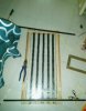
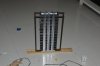
The magnets I use in this project are 4cm by 2cm by 1 cm in dimensions. Per speaker, I employ about 52 magnets. Their arrangement differs from the conventional speakers since I didn't want to use glue. So I made 2 frames out of MS that I had used for my first ribbon - 43 cm by 25 cm. I then placed N-S-N-S magnets across the frame which solves the problem of glue and also prevents the magnets from flying away from its adjacent partner in the column. MS frame also holds the magnet down. The drawback of this approach is definitely the lower magnetic field you get since we are 'shorting' opposite poles. None the less my priorities can afford to over see these drawbacks, at least for now.

For the conductor design I decided to pursue the route of matching the impedance of my super cheap 'Jansen' amp - 4 ohms. The task of cutting alu foil to 4mm and sticking one strip at a time on the cello-tape (great way to test your patience) is a rather stressful but I am used to it now. The below link is the calculator I used for the impedance.

I will explain how to use this calculator. Its fairly easy. I believe it used the formula of Resistivity that is R= Rho*L/A. You need to just input length, width and thickness of your conductor. The length of my conductor is around 47 cm pre-corrugated and 43 cm after corrugation, which is also the length of the frame. I use 3 strips of cello-tape with 4 strips of 47 cm long alu-foil corrugated per strip. So the length is 47 cm*3*4 = 564 cm. The thickness is 11 micron (the thinner the foil the higher is the impedance) and width of one strip is 0.4 cm. This gives me a value of 2.2047 Ohms. Mind you this calculator is for trace resistance of copper clad boards and hence you need to multiply the result with 1.585 which is the ratio of resistivity of Alu to Cu. Therefore, I have around 3.5 ohms and I am pretty sure this is acceptable for the 4 ohm amp.

Clemson Vehicular Electronics Laboratory: Circuit Board Trace Resistance Calculator

For more details refer picture.

Cheers,
 

Attachments

  • DSC_0257.jpg
    DSC_0257.jpg
    11.6 KB · Views: 45
Last edited:
The Marantz PM7000N offers big, spacious and insightful sound, class-leading clarity and a solid streaming platform in a award winning package.
Back
Top