DIY powersupply

suraj

Active Member
Joined
Feb 26, 2013
Messages
103
Points
28
Location
Mysore
Hello
I need a Desktop power supply,mainly to power a buffered headphone amp(basically a watered down pimeta clone).I was using 9v batteries(2x9v for 18v) to supply it,but due to the batteries running out fast,and good 9v's being expensive over a long period,i decided to make my own power supply.
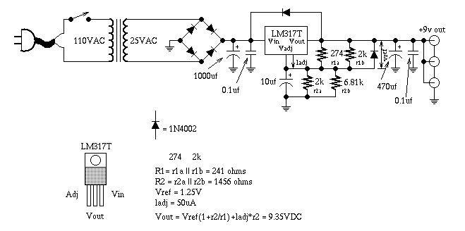
I did a little digging and got a schematic for a powersupply using a simple lm317 from Warren Young's website,his TREAD PSU.

i am using the recommended parts,except that i have substituted for th tantalums as i couldnt find 35v tantalums locally(all i have are 16v tants)

the schematic is this
87459900.png

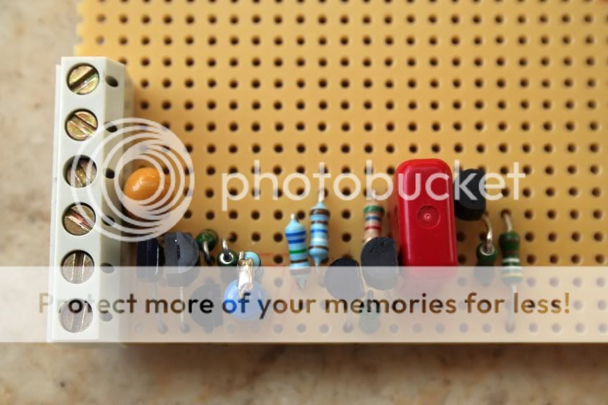
and this is the pcb layout made in Eagle free edition
29645215.png


all i did was copy Tangent's layout,replicate it in eagle and convert the PCB to single layer from his double layered one.

I am going to use an IEC socket with a fuse holder for power entry.
This will go to a 10A rated Delta EMI filter to filter the AC supply
then I am going to use a 220/18-0-18 1A transformer for stepdown.
and this AC goes to the circuit,which is rectified and regulated
All this will be on a etched on a standard single layer pcb,and the tracks given a thick solder coat for current capacity boost.

How good is the circuit?Tangent has given very low ripple values for this,0.0068mv,and i feel diy power supplies on a shoe string budget cannot get better.

I am limited to single layer pcb's as i cannot etch double layer ones,nor do i know if it is possible to make double layered ones professionally for cheap.

I am making this a single rail PSU,with an output of hopefully 15-12v.
If this goes well,i want to try out a +15v -15V dual supply.

Omishra had suggested some psu's in a previous thread
1 PCS Power Supply PCB, for High Power Audio Amplifiers DIY. SKU159005 | eBay
Power Supply Board Kit, PCB, Based on LM317 & LM337 IC | eBay
+15V -15V 0.2A LM317 LM317 Power Supply PCB for audio Diy | eBay

but these seem a tad too expensive for what they offer and are pretty much similar to what i am doing.
Also,since i already have all the parts i need,its not much of an expense except going to get the toner transfer print.

So,Shall i go ahead with this?

Also,since there are so many Different powersupplies in use in the DIY amps that many users have made,Can someone suggest me better/improved designs with the schematics/PCB layouts?

I will make this powersupply since it is good enough,i feel,and it gives me a start in DIY powersupply.But,i dont know how it is going to turn out,and am looking to upgrade to better supplies if anyone is willing to share.

Kindly advise,
Thanks and regards
Suraj
 
LM317 is correct. Here is a circuit diagram. You can replace the transformer with 230V ==> 25V AC.

Ultra-Clean-9V-DC-Power-Supply-Guitar-Effect-Schematic-Diagram.PNG


Instead of LM317, you can also use IC 7809.
 
I chose the 18v transformer because i already have one.
Also,the circuit is the same as what i have done,only it uses fixed values resistors and cannot be adjusted.every thing else is the same i guess?
 
Bump!
Any designs/PCB's please?
I am open to buying pre-made PCB's too.

@Omishra,i came across this -
http://www.hifivision.com/diy/25760-diy-amplifier-gets-new-diy-power-supply.html

How good is it?I dont need the Large wattage,only good clean power for Dac and Amp combo.Reply please!

Also,Ive printed out my PCB.need to etch it out and test the ripple and output.
Also looking at geting authentic National LM317 over the generic ST one.will it be useful?
 
Last edited:
Bump!
Any designs/PCB's please?
I am open to buying pre-made PCB's too.

@Omishra,i came across this -
http://www.hifivision.com/diy/25760-diy-amplifier-gets-new-diy-power-supply.html

How good is it?I dont need the Large wattage,only good clean power for Dac and Amp combo.Reply please!

Also,Ive printed out my PCB.need to etch it out and test the ripple and output.
Also looking at geting authentic National LM317 over the generic ST one.will it be useful?
Suraj,

Look at your requirement from two angles -
1. High power low ripple for power amp
2. Low power but lowest ripple, lowest noise, mainly clean PS for preamp and source like DAC.

My PS in above like was for power amp. I built that for floating ground. It has benefits over using CT of transformer as ground.

For 2, I have designed this PS.

Lm317 is not that difficult to get, I source it from local industrial dealer.
 
Thanks!
Yes,2. is what i really need.and since you've built it like a tank,it should keep DACs very happy.
I read that the parts cost as of 2011 was rs750.
And,since i have all the parts i need,except for the MUR810s and the inductors ,it will be quite cheap for me to build it too.
So,do you or anyone else have left over PCBs for it?or,how much does the kit cost today?
Main thing is,i dont know where to get good Inductors.
So,how do i go about it?

Hi Suraj,
I have few Power supply kits.We call it OPS(Omishra's Power supply).One kit would cost you Rs1000 including shipping.You can see complete Power supply with R-core here Introducing the (mini) Tower of Power - AudioKarma.org Home Audio Stereo Discussion Forums

Regards,
Sachin
 
There are many modern mans supply circuits that are better than the 317 based ones
teddy prado , minireg , LED regulator to name a few , they will be better choice .....
check DIYa forums
 
There are many modern mans supply circuits that are better than the 317 based ones
teddy prado , minireg , LED regulator to name a few , they will be better choice .....
check DIYa forums

IMO you are talking few shunt regulators. 317 is KISS kind of regulator. There are many but marginal difference unless application like phono preamps. It depends on specific requirement - Constant current/voltage, line regulation, load regulation, noise floor and ripple rejection, ps impedance.
 
There are many modern mans supply circuits that are better than the 317 based ones
teddy prado , minireg , LED regulator to name a few , they will be better choice .....
check DIYa forums
Ive seen Teddy pardos before and they cost a fortune!

ok,i'll get straight to the point.
Thing is i have a half decent buffered headphone amp(a pimeta clone),and use cheap 1.8k Sony headphones (which i blew while testing) or if my elder brother forgets his cans at home,the Audiotechnica M50 or the HD598(?) .
So,i dont need high end PSU's(which exceed the cost of all the gear i have) just clean supply.

Now,being fuelled by pocket money,i am also low on budget,compared to the earning adults here,and,i am also venturing to make my own MYREF amp,so thats taken a considerable chunk of cash.

So,i want a decent supply,not high end,which is great for entry level audio, without compromising on quality.

Also,i have not decided which dac to do.I have a few pieces of WM8740 DACs(3 infact,just the IC) which were given to me.
I am stuck on whether it would be worthwhile to attempt a diy design or go for a proven professionally made board.more on this in a new thread.

so,i want a supply,which can feed the dac too,that is when i make the dac.
What sort of supply do i need for a dac?i mean,i read Omishra's post and its a bit too crazy.So,Dac quality powersupply,i'll leave this for when i make that DAC.

Constant current/voltage, line regulation, load regulation, noise floor and ripple rejection, ps impedance.
the electronics madams never even spoke of such stuff! :annoyed:

as of now,i will be happy with err...good enough power for my amp,so what do i really make?there are too many schematics and regulator models

Yes,infact i did check on the Minireg before,have given it some serious thought.but then,its quite premium and PCBs need to be bought,the parts to be ordered online.i already have the opamps and most of the parts needed for the minireg,only need good transistors and mkp caps.
I can attempt it,given it doesnt cost too much to make.

@Sachu888,I'll pm you
 
Suraj,
There are two basic kind regulators - Series(linear) and shunt. LM317 is linear regulator same as all those 78XX/79XX series regulators. But LM317/337 has lower noise floor. There are many shunt regulators they are discrete or Controlled by some OPAMP.

Don't take so much tension - simple PS with 317, decoupling from mains does good job. I have used these for phono stages which take <0.3-3mV input, but never got any hiss/hum, pink or white noise at output which was amplified to ~3.0V. Anyway you can go to more complex ones as per your convenience and budget.
 
We are using OPS with Phono preamps.They are very sensitive to noise.This is the best preamp power supply I have ever seen.

Regards,
Sachin
 
Hi all
What about this power supply.Using LM 317 and LM337 .Came in Elektor for a preamp.
 

Attachments

  • Power Supply Circuit Diagram.pdf
    26.4 KB · Views: 31
Hi all
What about this power supply.Using LM 317 and LM337 .Came in Elektor for a preamp.

Nothing wrong with that too, it has following differences -
  • RC snubber at rectifier didoes 1N4004 and not required if ultra fast diodes are used.
  • Additional transistor at Vreg pin of 317/337 which acts at slow start for output. Means it will reach to desired output voltage after time constant set by 47K? and 4.7F at base of those respective transistors (Please calculate, I am lazy). That transistor will conduct after that 4.7F Cap charges through 47K? (after base of transistor reaches >0.7V, IMO its after 10mSec). Missing protection diode for this Cap.
  • Its missing Vreg Cap which lowers noise floor and subsequent protection required from that cap discharging while powering off.

In OPS, we added input CRC for power bank and output LCL filter for regulator generated noise, if any. Also recommend R-core transformer for low noise requirement. which has smaller capacitive coupling for mains noise.
 
Last edited:

Keith, thanks for links and they are sensible mods. Technically it may be better in specs. You will find n number of mods for that Vreg Pin. I have also seen transistor/OPAMP servo control for that. It becomes near implementation of a shunt regulator in name of mod to linear one.
It depends upon ones use case. I have seen below certain level, our generic devices are immune to noise and ripple. So why go complex if it does not affect.
I agree. But you know, we "audiophools" always like to overengineer things. Whether it makes a difference or not is besides the point :eek:hyeah:
 
thanks for the links!very interesting.

yes om is right here the differnces will be minimal as it is power amp.
you can think of theready version of the 317s
teddy variants are not expensive : like this one A new regulator was born - pink fish media
something new to try out!:D

Ok,so while i get things in order to build a OPS,
i wanted to know a few things
1.i have a 100rs 18-0-18 1A transformer,E-I core.now,how much does a similar R-core or toroid cost?Would the R-core justify the cost of the gains?
And,how much of a hit do i take for using the cheap E-I core?will the gains from using OPS be negated due to the E-I core's defects?or will the OPS still give good quality supply?I am not talking of dac quality supply,only it needs to be good enough for entry level headphone audio.
2.How big is the pcb?
3.Wiring.I plan to make it like this
IEC socket(with fuse)->RFI/EMI filter->Transformer->OPS->output.

is this OK?
4.Fuses.Slow-blow i guess?is 250v 500mA enough?
5.will the EMI/RFI filter help in removing mains noise?
6.Where do i put the switches?If i get a IEC socket with a switch,there will be a switch before the unit input.
I also want to put a switch before the DC output of the OPS.
why?I thought-
first switch on mains->switch on unit supply->wait for a few seconds for supply to stabilise->switch on DC output to devices.

is this the correct method?or am i over thinking things?

Please advise

~~edit~~~
 
Last edited:
Join WhatsApp group to get HiFiMART.com Offers & Deals delivered to your smartphone!
Back
Top