Making of 'MY Double D' guitar distortion

kaushik

Well-Known Member
Joined
Mar 3, 2008
Messages
2,561
Points
113
Location
Bangalore
Project Log :
--------------------------------
Name: My Double D
--------------------------------

--------------------------------
The Idea :

--------------------------------
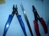
I wanted to make a decent distortion pedal for my guitar , at a lesser expense .
Also wanted some thing of small foot print.
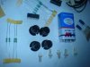
Online i got good reviews for the Double D . The simple design looked great ,
component count was less and .only 1 chip! CD 4049 ... power packed with six
inverters .

The URL [runoffgroove site]:Double D
Then i checked the sound clips ..online both modes sounded as pretty nice ;).
The kit should not cost more than 180Rs. leaving the cabinet and accessories .

------------------------------------------------------------------------------------------------
 
DAY1: Making of 'MY Double D' guitar distortion

DAY 1
12:46 PM 6/26/2008>
[Thursday]

-today is the first day
i just did the shopping[sp road]:confused: 
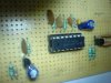
.. i hope all components are in stock
components alone< 100Rs i think:)
-getting the J-FETs was a pain ..i replaced the J201 with J 112

-i have laid one white paper on floor, placed the parts ..checked
taken the pictures
-read the runoffgroove.com author's page on my laptop ...the journey begins here ...!

------------------------------------------------------------------------------------------------
 
Last edited:
DAY2: Making of 'MY Double D' guitar distortion

9:38 AM 6/27/2008 >
DAY2

yesterday the following were purchased
-Capacitor box , all the reqd pf s , it was lacking some of the reqd values
soo i added the values ..
still some are missing line 47kpf etc ,plan to purchase today ...
-IC CD 4049 , J -FETs j112 [as a replace ment for the J109 ] ,vendor told it should match the
actual one upto 90%
-Ribbon wire 6 core , 1 mtr , for the pots ,
-Mic jack and socket , for testing phase i am using a cheap mic jack 10 Rs and Mic socket :)
-Electorlytics 10uf and 4.7uf ,diodes 1N4007 [for the soldering iron ..heh not part of original double d]
-A cutter and Stripper , to be used wire and leg cutter
-A soap box ...wait its a temporary cabinet to hold the SIX POTS ,and the mic jack ..battery etc what so-ever

- also a thin soap box is :) . easy to drill ... with the mosquito coils ..my new trick


The already exiting parts
- resistor box , still some missing values like 1 M , 2.2 M , 220K etc
soo i have to add today
-solder materials
-hook up wire , wires with one solid strand
-favicol, see below

-Added the components to the board [yellow verro board for a test run]


The disaster ..
My cheap [25 rs] soldering iron died ! :mad:
- so i i just the components are added to the verro board as per the plan in the website ,
This saves time !

- and i used *favicol* to hold them in place as i could not solder the components
[usually after the legs are bent and shortened they tend to fall out and if it happens will be a bigg trouble ]
-finally i was able to visualize how the assembled circuit will look after it is done

to do:
-Buy a good soldering iron , missing parts ,extra solder wires , shielded wires
-then the solder the board
-solder the ribbons to the pots ,fit in the soap box
-test by connecting to the pocket AMP
(...my secret tiny amp ..runs on 9V battery )

-Add a killer looking final cabinet ..keep watching
 
Last edited:
Day3: Making of 'MY Double D' guitar distortion

9:34 AM 6/29/2008 SUNDAY
DAY3

- Today I finished the assemblibng part and soldered all the components
- Just 2 Pots are conncted as I planned to test JIGGLE section
- A MIC Jack as input and output through a MIC socket

1 st test
- I have connected the unit to the 9v battery
- connected my guitar and MINI AMP from the out put
- "No sounds" !!! meaning 1 st test failed

I have made a list of tests to diagnose the problem
suspects > 1. DRY JOINTS ,My solder wire was very poor , all the time some coating settled n the Iron..i had to remove
that coat so as to make the soldering come in contact with the solder wire ...otherwise it does not melt '
2.MAY BE THE IC DIED : IC CD 4049 is a CMOS device..sensitive to temperature ... as i did lott of soldering in the past
i avoided to use a IC base ... may be during the asembly the IC died
3. May be the Supply, MIC connections ,OUT put connections

Diagnosis

- Tested the FETs by isolating and applying +ve gate voltage using 100K resistor ,a test LED comnected between Source and Gnd.
As i apply the +ve bias the LED glows bright ... soo FETs are alive !

- Visually checked the IC connections ....all ok ..

-Next I will do some electrical checks...:)...
notes:i have taken the pics ... my phone cable is missing soo assume "PICS COMING SOON .."


wanted : comments comments .. please
 
'MY Double D' guitar distortion in pictures so far

Tools and solder side
 

Attachments

  • DSC00393-400.jpg
    DSC00393-400.jpg
    12.7 KB · Views: 76
  • DSC00385-400.jpg
    DSC00385-400.jpg
    13.4 KB · Views: 75
'MY Double D' guitar distortion

Here is ......


LIST]
>MY SOLDRON
>COMPONENTS SO FAR ASSEMBLED
>THE PARTS -GALLERY

[/LIST]

you can see the soldron logo ....not burnt up after heating [means original :D ]
... parts including 2 pin connectors to make life easy ....
..i have kept some space between different circuit [ like the pre-boost ,inverters and post-mixer] sections so as to easily examine each one section in case of problems ...:)

....any suggestions??
 

Attachments

  • DSC00394-400.jpg
    DSC00394-400.jpg
    14 KB · Views: 75
  • DSC00396-400.jpg
    DSC00396-400.jpg
    17.2 KB · Views: 75
  • DSC00391-400.jpg
    DSC00391-400.jpg
    8.9 KB · Views: 75
Last edited:
great project. keep posting pics and details man. would love to see how it comes through. i might wanna try making one. also have you tried amp and effect modelling software?

keep up the great work!!

k
 
Order your Rega Turntables & Amplifiers from HiFiMART.com - India's reputed online dealer.
Back
Top