The " PFA TRIPLE 6005 "..... DIY tube amplifier of 2022.

drlowmu

Banned
Banned
Joined
Oct 28, 2020
Messages
721
Points
93
Location
Warrensburg, Missouri
This .................... is a never-before designed and never-before built tube amplifier circuit.

It is being built to be subjectively evaluated, by listening on high efficiency, large-radiating-surface loudspeakers, such as ALTEC or GPA models.

Up until now, ( in my estimation and opinion ), prior to 2019 the best compromise that could be done for powering ALTEC speakers with 15 inch woofers, was a simple two stage Direct Coupled Single Ended 2A3 amplifier with a " fast " extremely low DCR power supply, all things carefully executed.

In 2019, with the help of my audio mentor, I DIY designed and built a non DHT stereo amplifier, using inexpensive EH KT88s, that outperformed the creme of the crop in DHT 2A3s, the AVVT ( VAIC ) 2A3 mesh plate. How could a $41.00 USD indirectly heated tetrode tube ( operated as a tetrode ) beat out a $500.00 " holy grail " DHT 2A3 mesh plate triode AVVT?

The answer is very simple.


The DIY 2019 KT88 amp had a superior power supply execution.

It allowed the 2019 DIY amp to totally CRUSH the traditional accepted audio " stereotypes ", of

(1) Directly Heated Triode's supposed superiority VS: indirectly heated output tubes,

(2) A triode output stage's supposed superiority , VS: a non- triode, .........a tetrode ( tetrode - four elements not three ) operating as a tetode, with a separate G2 supply for the fourth element.

(3) The need for any Negative Feedback in a non-triode audio amplifier . The 2019 KT88 amp uniquely - had none !!


There was no denying what we heard, all four of us highly experienced amplifier builders present were in full agreement in this 2019 Montana listening evaluation.

What was this " superior power supply execution " in the KT88 amp, that produced such a profound audio performance difference ?

Four things :

(1) The KT88 amp used TWO 5U4GB tube rectifiers, each acting as a single diode, rather than one EH 5U4GB.

(2) B+ filtering to G2 and the plate resistor of the input/driver tube ( Ra ) , was TWO TIMES SHUNTED, one SHUNT after another ........in a series - connection, rather than a single SHUNT.

(3) B+ filtering to G2 and the plate resistor of the input/driver tube ( Ra ) was also TWO TIMES FINAL FILTERED ( as L1/C1/L2/C2 ) rather than a single FINAL FILTER ( L1/C1 ).

(4) The use of GTO caps to bypass C1 and C2, leading to the Output Transformer and Finals / Output tube stage.


The first numbered change above, halved the impedance of the rectification, and provided a wonderful-to-hear dynamic contrasting capability, with greater overall dynamics on musical transients.

The second numbered change above, lowered the impedances of the B+ supplies to these critical circuit points. The DOUBLED / SERIES SHUNTING was audibly superior in it's B+ support of the tubes !!!

The third numbered change above, gave a fantastic resolution to the audio signal, in the very first stage of the audio amp. Any loss of audio resolution / music information, that occurs in the input stage is never ever made up in later stages, is it ??

The fourth numbered change, GTO caps to the Finals, has been fully covered on HFV elsewhere previously.

You would all be amazed, totally amazed, to hear the resolution that a vacuum tube is capable of, once it is given a squeeky clean B+ feed. Unfortunately, no one in audio has seemed to do this, to the degree we have been since the 2019 KT88 amp. It is just taken for granted, and not understood !!! We've always done it " such and such a way " for the last 100 years, WHY should we change, and make the filtering more complex ?

The answer is simple, " because it is necessary...... for highest audio resolution. "

A further thought :

The gain of the Input tube stage in a two stage tetrode amp may be perhaps 35 times, whereas the gain of the Finals / Output tube stage may be 12 times. This gain difference to me, seems to make the Input stage three times more important, as far as having a " squeeky clean " B+, than is the Output stage !!! This three times is ALSO totally irrespective of the fact that if music information is at all " lost in the Input stage " it is never " made up later - in the Finals stage.

- - - - - - - - - - - - - - - - - - - - - - - - - - - - - - - - - - - - - - - - - - - - - - - - - - - - - - - - -

In 2021, on Hi Fi Visions, we have thoroughly documented my next major build, after the 2019 KT88 amp. The Stereo 6005 amp. The development of extensive quadruple filtering can be seen in the following posts, starting early on, on Page 2, Posts 23, 32 and 34. There exists a good summary on Page 3, Post 43. Here it is :


The only difference between then, early in 2021 on Pages 2 and 3, and later on, is that I reversed the order in a larger new chassis. The SHUNTS were first, and FINAL FILTERS in the last positions, two in series each, four total per B+ feed.

-- - - - - - - - - - - - - - - - - - - - - - - - - - - - - - - - - - - - - - - - - - - - - - - - - - - - - - - - - - - -

I am initially building only one monoblock chassis, which will be listened to in mono, driving pairs of ALTEC VOTT type speakers in two different locations.

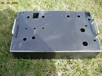
In the last week, I have invested well over twenty hours of labor, on a " blank " 14 gauge all-steel chassis with welded corners. Tedious labor with common hand tools. Here is what it looks like, as of 4-10-22 :
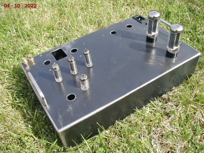
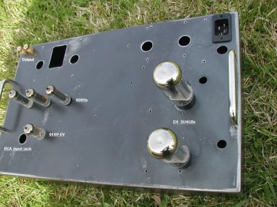
001  edited.jpg011  edited.jpg
010  edit 2.jpg


In another post, not here, I will write up all of the highly compelling reasons ( to me !!! ) for building the PFA TRIPLE 6005.

The " reasons" to build this amplifier post should truly put this new design in proper perspective. It is very exciting for us with larger format horn speakers !!!

Thank you for your reading time, and following along.

Jeff
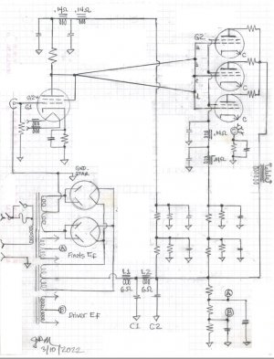


TRIPLE SNIP TOPOLOGY .- BLANKED OUT  USE.jpg
 
Last edited:
Design Philosophy and Technical Considerations of the new 2022 “ PFA TRIPLE 6005 “.


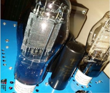
As pointed out above in this thread's first post, with a careful power supply implementation, we were able to get a $41.00 tetrode tube ( EH KT88 ) operating as a tetrode, to outperform a ?? $500 ?? VAIC AVVT 2A3 mesh plate tube run in triode mode. Mesh plate AVVT 2A3s are pictured below :


PR AVVT.JPG

My audio mentor and I also had an extreme interest in 6005 output tubes. Prior to my 2021 thread of a 6005 SE DC amp, I had built ( from 2014 on ) four different 6005 SE DC versions. None seemed totally convincing to me.

The 2019 KT88 SE DC amp was an eye and ear opener for my mentor and I.

As described in this thread's first post above, after our 2019 KT88 listening experience, we went to double 5U4GB rectifiers, double series SHUNT B+ filtering, and double series Dennis Fraker ( my mentor ) Final Filters ( L1/C1/L2/C2 ).

This doubling was instead of using single ( SHUNTS, Rectifiers, and Final Filters ) in each sensitive circuit position.

Dennis in 2020, applied this 2019 KT88's supply topology to a KT150 output tube. He found, when watching movie soundtracks, that the extra power of the KT150 was nicer to have, ( versus the 2A3 SE amps he had built since 1989 ). His larger KT150 tube also went lower than my EH KT88 tube...... in the same SE DC circuit.

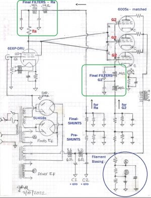
We see in this thread's first post that - for the 2021 6005 build - the “ performance started to click ” after I put a similar, more robust filtering complement into the amp's two most sensitive circuit positions. That would be double SHUNTING and double FINAL FILTERING - for the amp's Input tube's Plate resistor ( Ra ) and the Output tetrode's “ G2 ” element.

I am fairly sure, that no other amps in the history of audio, have ever done such filtering in such a quadruple topology PASSIVE manner . It is outlined schematically below : ( Pre SHUNT, Final SHUNT, Pre L/C filter, Final L/C filter. ) See :


TRIPLE SNIP TOPOLOGY .- BLANKED OUT  USE, edited 4- USE.jpg


This above B+ quadruple filtering topology, allowed for the fullest performance to date, from the small ( 12 Watt plate dissipation ) military- specified 6005 tube. It has taken me FIVE 6005 amp builds since 2014, to “ get it ”.

Subjectively the stereo 6005 amp of 2021 easily out-performed my 2019 EH KT88 SE DC amp by at least 20 percent !!!!!!!!! Mind you, in 2019, this KT88 amp “ readily outperformed ” a pair of expensive VAIC / AVVT mesh plate 2A3 monoblocks.

This unexpected audible result certainly begs the question “ How can a small 6005 tetrode power tube, costing maybe only ten dollars and sometimes less, outperform a VAIC / AVVT mesh plate 2A3 triode tube and / or, also my EH KT88 amp ?

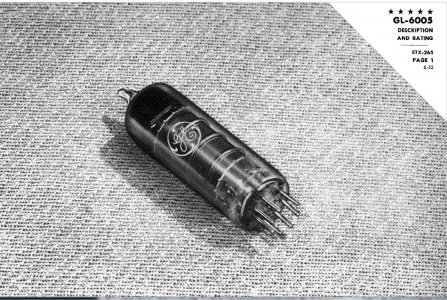
Subjectively, in my 2021 6005 build circuit, the 6005 seems to greatly outperform EVERY Output tube I have ever built with, or heard at audio shows !!! By a wide margin. I now think it isn't even close !!! Can I explain this? I will try, just a guess. Look at this photo of a 6005 tube :


Photo 1952 6005.JPG


What do you notice that is different in the above photo - from 99% of the tubes you will ever see???

That is right, the tube has a round plate structure. Almost all of the other output tubes we are familiar with have rectangular shaped plate structures. The 6005 has NO ninety degree corners to the shape of it's plate !! But this is only the beginning. The Control grid is round also. The cathode sleeve...... is also round.

This small ( circa 1951 USA-designed ) tube is totally symmetrical, unlike almost all other conventional receiving output tubes. It is much like the EIMAC family of USA-made transmitting tubes with round structures, only it conveniently operates at a lower and saner B+ voltages.

Also of critical importance : the elements inside a 6005 tube are very closely spaced to each other. This symmetrical AND closer element spacing seems to enable a far far better transfer efficiency, of the music signal, from the control grid, to the plate of the tube !!! The electron flow. Far less is lost in transfer, and FAR more music gets reproduced by the speaker. Astoundingly so to me, on my reference recordings.

There are many many unusual things going on sonicaly, when I hook these latest 6005 amps up to VOTT A7-8s. No other output tube, comes close, in transfer efficiency to the loudspeaker, and this is a wonderment and joy to hear and experience on one's most familiar recordings. The music uniquely “ jumps out ” of the VOTT ALTEC loudspeaker,........... cohesively.......................... in all three axis........ X,Y and Z.

l
- - - - - - - - - - - - - - - - - - - - - - - - - - - - - - - - - - - - -


Wait a moment. We are not quite finished doing this “ TRIPLE ” topic justice. I need to discuss zero feedback tetrodes ( VS a 2A3 triode ) and parallel SE tube stages next :


It is well known, that a triode tube can work acceptably with zero negative feedback, and be low in distortion. Almost all EEs will tell you that a tetrode or pentode ( tube types with more than three internal elements ) require some form of feedback. It has higher distortion inherently, when the tube is being asked to deliver higher power.

Can anyone please show me one modern schematic " with no negative feedback ", of a commercial tetrode or pentode amp !!! I have as yet .......to see one.

Since my first tube amp design in 1982, I have never used negative feedback loops in any of my amplifier designs. I do not approve of it - musically. My recent amps are designed for high efficiency ALTEC - type horn speakers. This speaker usually operates in my listening room at half a Watt, and often less.

With 225 VDC plate-to-cathode, and 32 to 33 milliamperes, we probably achieve 3 Watts output from a single 6005. With tetrode operation, and zero feedback, any 6005's power level above 1 Watt, and up to 3 Watts will have audible and increasing distortion. Offsetting this, however, is the 6005 tube itself - being symmetrical and having close spaced elements. With it's high transfer efficiency, it performs so effectively with my circuit, that I can easily live happily with a single tube per channel playing A7-8 VOTTs


QUESTION : What happens with the “ PFA TRIPLE 6005 ”, a Single Ended Parallel output circuit ???


1) Maximum power increases from a single tube at 3 Watts, to three tubes and 9 Watts maximum.

2) Distortion is cut to one third. Distortion will increase not starting at one Watt, but with three tubes sharing the load, it may increase starting at 3 Watts. This is well below the power level used 99.95 % of the time on many high efficiency speakers.

3) Impedance of the Output stage is reduced by a factor of three !!! This is exactly what a 15 inch large-radiating-surface-area woofer ( ALTEC 416B or 515B, etc. ) would LOVE to see. It controls the woofer in an unusually superb manner. This will play maybe an octave lower than a well set-up single KT150 SE DC amplifier.


PARALLELING of RECTIFIER and OUTPUT TUBE STAGES :


RECTIFIERS :


In high end tube design, it is generally not a good idea to parallel multiple tubes in any stage. Each separate vacuum tube amplifies the signal just a tiny bit differently from the other, and when operating in parallel, there is slightly less purity ( compared to a single tube ). This is due to skewing – differences between slightly unlike tubes. It is always audible, as a slight sonic degrade in purity, subjectively, perhaps a two to three percent degrade.

Starting with the 2019 KT88 designed stereo amp, I paralleled EH 5U4GB rectifier tubes. A 5U4GB is a directly heated rectifier, and as such, it has an instantaneous pulse response, VS. a rectifier with a cathode.

My power supply to the output stage is called a L.S.E.S. supply, meaning it uses low DCR small chokes and small all-film supply capacitors. ( L.S.E.S. is Low Stored Energy Supply ) These small film caps, often 50 uF or so, act more like a source-feed supply, rather than a conventional amp with larger caps, acting like a large storage reservoir of energy. The L.S.E.S. Supply uniquely does not have a thumbprint , or time continuum applied to the amplifier when playing back music. The L.S.E.S. supply, plays music in the time of the music, and NOT , as all other amps, in the time of a large storage reservoir of capacitance. It is a “ fast ” supply, that uniquely stays out-of-the-way of the pulsed conditions, found in real music .

A 5U4GB is specified to be able to do 4.7 Amperes of Instantaneous Peak current. When I parallel two 5U4GBs, I have the capability of doing 9.4 Amperes of Instantaneous Peak current. With a L.S.E.S. Power supply, employing two six Ohm ( !!! ) filter chokes, small/ fast film caps, and extra-ordinary Mil Spec internal wiring, the 100% improvement of Instantaneous Peak current capability, more than makes up for the 2 to 3 percent loss in purity when paralleling. It becomes a “ must have ” for rectification, ( at least for my type of fast / L.S.E.S. audio power supply. )

It is an amazing difference, to hear how much DYNAMIC music expression and contrasting is possible, with this type of supply circuit. The 2019 KT88 amp ABLY showed that to all four of us attending our A-B sessions. These new 2021- 2022 6005 amps all do these same good things on High Efficiency speakers. Bravo.


THE OUTPUT STAGE :

All small powered single ended amps suffer, to one degree or another, when trying to play orchestral crescendos. SE tube owners do not notice it much, or will be willing to accept this, because their amp plays so well, all the rest of the time.

My audio mentor went from decades of using 2A3 tubes, to a KT150 Output tube in 2020. Overall, when listening to “ bombastic ” movie playback, he preferred the slight extra power of the KT150 tube, even though it had slightly more distortion than his 2A3 SE DC Triode amps. Both amplifier types had zero negative feedback. This impression of his was after a year of him listening and comparing these two types of amps, as of March 2022.

After my mentor heard of my positive reactions ( of the 2021 Stereo SE 6005 amp ) and how much the 6005 tube itself impressed me in the new circuit, my mentor suggested that I design and build a “ TRIPLE 6005 ” output stage. The reason was that it will have three times the maximum power ( ~ 9 Watts ) , about three times less ( tetrode ) no feedback distortion at the levels it is used at, and that it will have 1/3 the impedance of a single 6005.

He pointed out, one third the impedance is EXACTLY what the large 15 inch ALTEC type woofers would LOVE to see. Low impedance drive will provide wonderful speaker control for our 15 inch woofer, when powered by a tube amp.

Of course, all three 6005 output tubes will need to be carefully matched, primarily so that they draw the same currents in the circuit. We have additionally applied in-circuit output tube “ balancing ” techniques, passive, …........to enable “ SEP ” or Single Ended Parallel operation.

The KEY question I have, of this entire design is :

“ Will the small purity detriment of paralleling output tubes be more than be offset, many many times over, by the specific use of the high-performing and great sounding 6005 output tubes ?? ”

From the 2021 6005 stereo amp build / listening experiences, I am willing to give this PFA TRIPLE 6005 a build and a try. My mentor thinks it will be the last design I will ever want to do !! I personally believe the 6005 tube itself, as used in my circuit, easily out plays every output tube I have experienced over my lifetime . So, dear friends, I am willing to build the PFA TRIPLE 6005. It simply..... has to be done.

“ To be, or not to be, that is the question . ”


Several people have asked me “ What does PFA stand for? ”

I honestly do NOT yet know the answer. Not until after I build and listen to these newest TRIPLE 6005 amps.

If it sounds as I now expect it will, “ PFA ” will nicely stand for “ PERFECT For ALTEC ”.

If it is at all disappointing, “ PFA ” will stand for “ Pretty Foolish Activity ”.

Thanks so much...... for following along !! Much thinking goes into a design. It is fun.

Jeff
 
Last edited:
I am looking forward to the outcome of your efforts.

N


Hello.

Thanks for the encouragement Vatron.

DIY is a little bit different, when one designs from scratch, with many never-done-before and logical reasons to do so,............ rather than simply copying someone's existing schematic.

Not pointed out above, this design will use a new - to - me Input / Driver tube, that gets glowing reports from it's users.

The 6E6P-EV or the 6E6P-DRU ( and it's " first cousin " the similar 6E5P ) are uniquely-designed Russian Military tubes. It is a highly special design, with a huge cathode to emit electrons, and a extra-large gold-plated frame grid. Mu of about 35, linear, powerful, well made, and not expensive.

A military tetrode, that is triode connected and triode operated. It is like having a Ferrari ....................for a five dollar cost.

One of the nicest and most reliable people in high - end tube audio, JAC of JAC Music, had this to report in 2016 about these particular Russian designed tubes :


Dennis, my audio mentor, has been using this input tube to drive a SE DC connected KT150 since 2020, and tells me it is the best sounding driver tube he has ever experienced.

Imagine this : a 6E6P-DRU, powered by a a squeeky clean B+, operating directly coupled........ into 6005s .

Jeff
 
Last edited:
That driver tube looks very interesting. As stated by Jac, "A fantastic driver, or head phone tube, and you can get a few Watts out of it, single ended" This sounds like a versatile tube, that is very capable of in many applications.

Just curious, what out put transformer impedance is required to drive three 6005's in parallel?

Mr. Vatron,

The 6E6P series tube has a large and enthusiastic following on line.

The LSES power supply can drive many Zs, so it is not as critical IME.

Usually, we like 5,000 Ohms for a single 6005. So three would be one third, or 1,667 Ohms.

A favorite beefy Output is the Hammond 1627 SEA, simply a fabulous sounding unit !!

It is 2.5K Ohms. I will operate it on the 16 ohm Output tap, using the entire secondary winding. It weighs 11 pounds, and can do 120 mA. unbalanced. That particular Output can do 2A3s, KT88s, KT150s, and three 6005s !! Enough tube choices for me.

A 1627 SEA is in a class by itself, performance wise.

It can slightly out-perform the third level ( top level ) Monolith Magnetics SE output, at 16 times the Hammond's cost. ( That is some " juicy" information for you !!!!!! Determined over a six month test period , on good gear, GPA 604 MLTL speakers, etc. )

Jeff

 
Last edited:
05 - 18 - 2022 ..................................PROGRESS REPORT, the " TRIPLE "

I have spent more than the last month, drilling and tapping many many holes in the two 14 gauge steel chassis, and Greenlee chassis punching larger round holes, for the tube socket locations, etc..

Today, these new style monoblock chassis were delivered by me to the Powder Coating shop, for sand blasting and powder coating ( Midnight Blue Wrinkle ).

When they come back, and are ready for assembly, I will post pictures of them here.

Also, I will count the number chassis holes I executed with hand-held electric drills, in each chassis. This work and effort was truly a tedious one. This is the last time I will do it this way. Cad Cam and precise Lazer metal cutting , ( as done for all the 2021 6005 Stereo SE DC Amps ), is THE best overall way to develop such a chassis, IMHO.

Jeff
 
5-21-2022 ........ Bypassing of the Rk in SE tube amps.......................for the " TRIPLE " 6005 monos


I have often mentioned that for really superior audio quality, EVERYTHING you do in a tube amp's Input stage is hyper-critical.

Are you getting tired of me writing " if you lose music information in the first stage, it will never be regained, later in the amplifier's circuit ". This is undeniable - common sense, and oh.... so true.

So what can we do, to optimize the Input stage as best as possible?

Several areas must be carefully implemented to maximize fidelity. Quickly coming to mind are these following areas :

The B+ feeding the Input tube
The wiring, into and out of the Input stage
The Plate resistor ( Ra )
The tube choice itself, including it's operating points
The Cathode resistor ( Rk )
The Cathode resistor's bypass Capacitor ( if employed )

Herein, I will discuss the last two areas mentioned above :

the Cathode resistor, aka Rk,

and if used, it's bypass Capacitor.


I chuckle to myself when people who own tube equipment " roll tubes" to obtain better sonics. The vacuum tube, while important, is only PART ( one of six things ) that we hear. All of the above six parts, associated with that tube is ALSO what we are listening to, all the time.

Of course, it is common sense one should seek to optimize both of an Input tube's associated resistors ( Plate resistor Ra and Cathode resistor Rk). Use the best sounding and highest quality resistors one can source and afford. Each of these two resistors' degree of goodness, ( the Ra ad Rk ) is something we hear continually and consistently, as the loudspeaker plays back music to us !!

Lets get into this, areas five and six :


The Cathode Resistor ( Rk )

For the input tube of a tube amp, the voltage across the Cathode resistor ( Rk ) is measured from the tube's cathode assembly to ground. This is typically a low voltage. I would estimate it to be in a range of 1.5 VDC to 6 VDC typically. This means that, with a typical current for said tube, there is not a lot of power dissipated across the Input tube's Rk.

Thus we can use lower powered resistors, which opens the door to a wide variety of different resistor choices, many which are very high quality and most important of all, have inherently good sonic attributes.

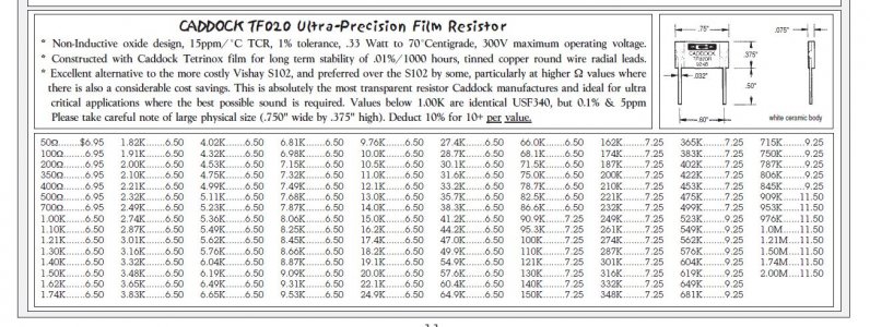
For Rks, several truly good resistor choices exist, and my number one favorite in 2022, is a Caddock TF-020. I know other DIY builders will have their favorite choices, but this type is mine ! YMMV. Fine !

Criteria I consider, among others, are the Rk's perceived bandwidth, dynamic contrasting capability, general quietness , capability to do timbres properly, transparency, neutrality or lack of signature, etc. Notice my use of the word perceived.
After you do the ordinary and necessary objective E.E. considerations, the real determination of an Rk, truly the most important of all, is how the resistive part subjectively plays music to one's ear !!

Great audio design when applied to resistors goes far beyond the existing Ohm's law formulas, math, proofs and textbook theories. Great audio design is really executed by some, superbly by ear, at a subjective and at an artistic level. Amen.

My first audio mentor once wrote " Scientists don't pursue the truth, it pursues them " ( Robert W. Fulton, circa 1970s ) . " The proof of the pudding, is in the eating " I say.


Caddock TF020  .33 Watts.JPG


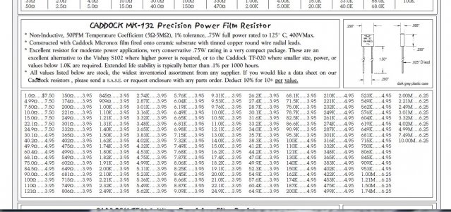
For a wider range of lower Ohm values, one may consider Caddock's MK-132 series below, which also has a higher power rating, of 0.75 Watts.

MK-132 0.75 Watts.JPG

The new 2022 " TRIPLE 6005 " build will employ two closely matched pairs of Caddock MK-132s, to obtain a very specific and desired Rk, having a low Ohmic value.


The Rk's BYPASS CAPACITOR

This is a sad area for me to bring up and discuss.

The Rk resistor's " bypass " capacitor, typically attaches from one side of the Cathode resistor - connected at the tube socket ( at the tube socket's Cathode Pin ) , and to the resistor's other side, typically and usually leading to ground.

This Rk bypass capacitor is IN the audio circuit, and it's quality, or lack thereof, is intimately tied to the ultimate goodness and fidelity of a SE tube amp's sonic presentation. The Rk bypass capacitor is highly audible !!

To obtain maximum possible fidelity, great care must be taken in implementing the Input tube stage's Rk bypass capacitor. The Rk bypass capacitor is one of the six areas mentioned as needing thoughtful optimization, at the beginning of this post.

Sadly, and for a variety of reasons, probably 99% of the Manufactured / Commercial tube amps in this world, use an electrolytic capacitor to bypass any Rk Resistor !!!! Remember, a Rk's bypass capacitor in IN the audio circuit. Let me ask you all, would you really want to own a tube amplifier that used an electrolytic as a coupling capacitor between two of it's audio stages ?? Probably not !! What would you really want there? Answer, as good of a film cap as one can afford and install, space wise.

See where I am going here ? Since the Rk bypass capacitor is IN the audio circuit, careful attention must be paid to its size and composition, IF you seek highest performance from your audio amp.


( 1 ) The first necessity, is it must be a film type cap, of ultra high performance, possessing total fidelity.


(2) The second necessity is it must be properly sized, in terms of total capacitance, or amount of microfarads ( symbol is uF ).


Point (1 ). “ Ultra high performance ” and “ total fidelity.”

This above description eliminates any use of a single Rk film bypass cap.

Why? Simple. Because no single cap exists yet in this world, that produces total fidelity in all parts of the music spectrum.

It takes a main film cap, and then multiple carefully chosen smaller film caps, carefully arranged in parallel, to enhance how any single film cap plays back music.

This multiple film cap paralleling technique is called “ film cap bypassing.” Almost every tube amp uses ONE capacitor in a capacitor location. People who know how to multiple film cap bypass, may use anywhere from two to seven different paralleled caps, in the usual single capacitor position in the circuit. This determination depends upon their skill level, and multiple caps are all selected VERY CAREFULLY, by ear , while listening to musical instrument playback.

In film cap bypassing, different film cap capacitor values tend to enhance different parts of the musical spectrum.

As a general rule, the smaller the microfarad value ( uF value ) of the film cap, the higher in frequency response will it actively enhance in conjunction with the original ( or main ) large value film cap.

If you combine a large main film cap, and parallel a very small value film cap across it ( say a 15 uF and 0.01 uF ) you will likely only enhance only with that 0.01 uF addition - the top – most frequencies of that two- capacitor combination. You will also possibly / probably create an audible hole in the linear response of that two-caps' music presentation. In a certain way, it will sound worse, than the original large film cap, used by itself.

Now, use some smarts. Listen to the two in parallel, and the one alone. Learn what each combo sounds like.

What can you do, to keep the improved top end response of the two-cap combo, with 0.01 uF added to the 15 uF main cap ??? The answer is NOT to give up, as most will do, BUT FILL IN THE PERCEIVED HOLE !!!!! That is easy to experimentally do. Select film cap sizes ( in microfarads or uF ) somewhere between 15 uF and 0.01 uF, to more linearly enhance the single film caps perceived music making capability.

Are you now missing the ultimate in midrange TOTAL beauty ?? If you know what uF value plays the mids the best, select the HIGHEST quality cap in that specific value, add it to the other two, and listen to a three-some film cap combo.

Recall, from my prior posting in the last two years, 0.22 uf is subjectively almost the " perfect-to-use " midrange enhancement value. If you strive for the ultimate in fidelity, cost no object, I would highly recommend using a Mundorf Supreme 0.22uF at 1000 VDC Silver and oil capacitor. It is also perhaps Mundorf's best sounding cap value, in their “ Supreme Silver and Oil ” line. ( This, I speculate, is often a function of many things and especially the cap's size relationship, diameter to length .) A second ultra high fidelity midrange bypass choice is a Dynami Cap E 0.22uF cap value – hard to beat . Truly superb. On a budget ( I am ), use a WIMA FKP-1 0.22 uF at 1250 VDC. All three of these suggestions - are proven solutions.

Now. Listen very carefully to how the three cap bundle plays back musical instruments. What are you hearing ?? Is there anything that suggests to you that still a smaller “ hole ” exists in the music's play back response?? If so, fix it, DO NOT GIVE UP.

With a 15 uF, 0.22 uF, and 0.01uF trio, I would suggest there will be a hole in your perceived response, readily audible, between the 0.22 and 0.01 uF values !!! This hole will be noticeable in the lower treble area of all musical instrument playback. FIX IT. Try adding a high quality 0.033 uF film capacitor there, for the lower treble's uniform and ultimate music playback augmentation.

Now, listen carefully to the four caps in parallel. Does any area not play as beautifully, as all the the areas you have augmented?? If so, FIX IT.

( Likely you will need to fix the mid-bass regions, to get that area to play best, and equal to the rest of the optimized capacitor. Look at my HFV amp build photos over the last two years, and discover what value plays the mid bass. )

- - - - - - - - - - - - - - - - - - - - - - - - - - - - - - - - - - - - - - - - - - - - - - - - - - - - - - - - -


How and where one connects all of these various multiple film bypass caps is also of PRIME importance !!


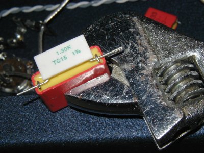
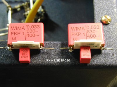
The smaller the uF value, the closer it needs to be located and connected to the Rk , “ to DO something ” !!! Ideal execution theoretically for smaller value film capacitor bypasses is “ zero lead length ”. A utopian impossibility in most instances. Below, from my HFV 2021 6005 stereo amplifier HFV build thread build, are photos. It shows that favorite Caddock TF-020 ( 1.3K - for the 6N23P's Input tube's ) Rk, with some of it's smallest value bypass caps attached.

( I decided to discreetly file some of the plastic, off of parts, to make parts fit as intimately as I wanted them to, prior to soldering. )

Observe :


003.JPG
The crescent wrench above holds the parts above during assembly. It worked !! See below.


021  edited.jpg


The larger film bypass caps for each of the above two Rks, weremounted on a Keystone Board Bracket, using Keystone 817 terminals, with doubled up ( for transfer efficiency ) runs of 19 AWG Wonder Wire ( wire with silver content ). This Wonder Wire connected the larger bypass capacitors' positive and ground return terminals.


Point ( 2 ). The best sized / uF value film cap.

To wrap-up this section on “ Rk Bypass Capacitors”, I want to address the issue of the uF size of a bypass cap. A person usually applies a complex E.E. formula, to nicely match the – 3dB down point, formed by the Input tube's Rk, and it's associated bypass capacitor.'s uF size. In almost all cases I have seen, the designers IMHO choose a too low frequency, which requires a “ too large” in uF value, of a Rk cap.

Unlike common practice, my mentor and I tend to select the size of the Rk bypass cap, incrementally by ear, such that it is as small as possible, without sacrificing adequate low end. I sometimes think that " the larger the cap is " in uF, the more difficult it is to power the Rk capacitor, by the tube, by it's cathode. So, I try to optimize the value choice, incrementally, by bracketing the bypass cap's total optimal size, by ear.

Additionally, I am very sure the quality of the Rk bypass cap, and how well it is executed, is the most important factor of the capacitor when used as a Rk bypass, in a high quality audio circuit. I am very sure of this. From direct listening experience, I find that the uF size needs to be selected by ear, and is a less-important factor than the quality of the cap. Few people do such subjective listening evaluations, and so, most are unaware of this as a path to sonic optimization. What sounds best? Isn't that the goal ???


I am excited about building the 6005 TRIPLE amp this year, employing all these techniques discussed herein. The two mono chassis are at " Sure-Coat " the Powder Coating shop presently, for sand blasting and powder coating. Stay tuned !!

Jeff
 
Last edited:
Wouldn't a better approach to finding these "holes" in the audio spectrum allegedly produced by a single bypass capacitor be done by looking at a frequency sweep and measuring the level deviations? To be clear I mean a true frequency sweep, not pink noise on a spectrum analyzer because that would be too course. A computer with a good sound card or USB audio interface and some freeware can plot the response. Yes in the end the ear is the final arbiter, but measuring first will give us a one time view of all the problem areas, if they do exist.

Another problem with selecting parts solely by ear is personal preferences. If this is a personal build, that may be fine. But a manufactured amplifier must be flat across it's bandwidth within established tolerances. It is up to the user to select speakers to match their tonal preferences or even use equalizers to get the sound they want.

And what do you do about the parallel resonances induced by parallel connected capacitors? You may be hearing this effect as well and perhaps again that suits your speakers or listening preferences. But in other situations this could be a sonic detriment.
 
Last edited:
Another problem with selecting parts solely by ear is personal preferences
Is the age of the ear taken into consideration? If one goes through so much pain in bypassing capacitors what about bypassing the ears with those with younger years?
 
Is the age of the ear taken into consideration? If one goes through so much pain in bypassing capacitors what about bypassing the ears with those with younger years?
Well that's also a very good point. Tailoring the amp by ear is fine for personal use but a manufacture has no idea of a potential customers age. So they need to make the amp as flat as possible.
 
5-21-2022 ........ Bypassing of the Rk in SE tube amps.......................for the " TRIPLE " 6005 monos


I have often mentioned that for really superior audio quality, EVERYTHING you do in a tube amp's Input stage is hyper-critical.

Are you getting tired of me writing " if you lose music information in the first stage, it will never be regained, later in the amplifier's circuit ". This is undeniable - common sense, and oh.... so true.

So what can we do, to optimize the Input stage as best as possible?

Several areas must be carefully implemented to maximize fidelity. Quickly coming to mind are these following areas :

The B+ feeding the Input tube
The wiring, into and out of the Input stage
The Plate resistor ( Ra )
The tube choice itself, including it's operating points
The Cathode resistor ( Rk )
The Cathode resistor's bypass Capacitor ( if employed )

Herein, I will discuss the last two areas mentioned above :

the Cathode resistor, aka Rk,

and if used, it's bypass Capacitor.


I chuckle to myself when people who own tube equipment " roll tubes" to obtain better sonics. The vacuum tube, while important, is only PART ( one of six things ) that we hear. All of the above six parts, associated with that tube is ALSO what we are listening to, all the time.

Of course, it is common sense one should seek to optimize both of an Input tube's associated resistors ( Plate resistor Ra and Cathode resistor Rk). Use the best sounding and highest quality resistors one can source and afford. Each of these two resistors' degree of goodness, ( the Ra ad Rk ) is something we hear continually and consistently, as the loudspeaker plays back music to us !!

Lets get into this, areas five and six :


The Cathode Resistor ( Rk )

For the input tube of a tube amp, the voltage across the Cathode resistor ( Rk ) is measured from the tube's cathode assembly to ground. This is typically a low voltage. I would estimate it to be in a range of 1.5 VDC to 6 VDC typically. This means that, with a typical current for said tube, there is not a lot of power dissipated across the Input tube's Rk.

Thus we can use lower powered resistors, which opens the door to a wide variety of different resistor choices, many which are very high quality and most important of all, have inherently good sonic attributes.

For Rks, several truly good resistor choices exist, and my number one favorite in 2022, is a Caddock TF-020. I know other DIY builders will have their favorite choices, but this type is mine ! YMMV. Fine !

Criteria I consider, among others, are the Rk's perceived bandwidth, dynamic contrasting capability, general quietness , capability to do timbres properly, transparency, neutrality or lack of signature, etc. Notice my use of the word perceived.
After you do the ordinary and necessary objective E.E. considerations, the real determination of an Rk, truly the most important of all, is how the resistive part subjectively plays music to one's ear !!

Great audio design when applied to resistors goes far beyond the existing Ohm's law formulas, math, proofs and textbook theories. Great audio design is really executed by some, superbly by ear, at a subjective and at an artistic level. Amen.

My first audio mentor once wrote " Scientists don't pursue the truth, it pursues them " ( Robert W. Fulton, circa 1970s ) . " The proof of the pudding, is in the eating " I say.


View attachment 69417


For a wider range of lower Ohm values, one may consider Caddock's MK-132 series below, which also has a higher power rating, of 0.75 Watts.

View attachment 69421

The new 2022 " TRIPLE 6005 " build will employ two closely matched pairs of Caddock MK-132s, to obtain a very specific and desired Rk, having a low Ohmic value.


The Rk's BYPASS CAPACITOR

This is a sad area for me to bring up and discuss.

The Rk resistor's " bypass " capacitor, typically attaches from one side of the Cathode resistor - connected at the tube socket ( at the tube socket's Cathode Pin ) , and to the resistor's other side, typically and usually leading to ground.

This Rk bypass capacitor is IN the audio circuit, and it's quality, or lack thereof, is intimately tied to the ultimate goodness and fidelity of a SE tube amp's sonic presentation. The Rk bypass capacitor is highly audible !!

To obtain maximum possible fidelity, great care must be taken in implementing the Input tube stage's Rk bypass capacitor. The Rk bypass capacitor is one of the six areas mentioned as needing thoughtful optimization, at the beginning of this post.

Sadly, and for a variety of reasons, probably 99% of the Manufactured / Commercial tube amps in this world, use an electrolytic capacitor to bypass any Rk Resistor !!!! Remember, a Rk's bypass capacitor in IN the audio circuit. Let me ask you all, would you really want to own a tube amplifier that used an electrolytic as a coupling capacitor between two of it's audio stages ?? Probably not !! What would you really want there? Answer, as good of a film cap as one can afford and install, space wise.

See where I am going here ? Since the Rk bypass capacitor is IN the audio circuit, careful attention must be paid to its size and composition, IF you seek highest performance from your audio amp.


( 1 ) The first necessity, is it must be a film type cap, of ultra high performance, possessing total fidelity.


(2) The second necessity is it must be properly sized, in terms of total capacitance, or amount of microfarads ( symbol is uF ).


Point (1 ). “ Ultra high performance ” and “ total fidelity.”

This above description eliminates any use of a single Rk film bypass cap.

Why? Simple. Because no single cap exists yet in this world, that produces total fidelity in all parts of the music spectrum.

It takes a main film cap, and then multiple carefully chosen smaller film caps, carefully arranged in parallel, to enhance how any single film cap plays back music.

This multiple film cap paralleling technique is called “ film cap bypassing.” Almost every tube amp uses ONE capacitor in a capacitor location. People who know how to multiple film cap bypass, may use anywhere from two to seven different paralleled caps, in the usual single capacitor position in the circuit. This determination depends upon their skill level, and multiple caps are all selected VERY CAREFULLY, by ear , while listening to musical instrument playback.

In film cap bypassing, different film cap capacitor values tend to enhance different parts of the musical spectrum.

As a general rule, the smaller the microfarad value ( uF value ) of the film cap, the higher in frequency response will it actively enhance in conjunction with the original ( or main ) large value film cap.

If you combine a large main film cap, and parallel a very small value film cap across it ( say a 15 uF and 0.01 uF ) you will likely only enhance only with that 0.01 uF addition - the top – most frequencies of that two- capacitor combination. You will also possibly / probably create an audible hole in the linear response of that two-caps' music presentation. In a certain way, it will sound worse, than the original large film cap, used by itself.

Now, use some smarts. Listen to the two in parallel, and the one alone. Learn what each combo sounds like.

What can you do, to keep the improved top end response of the two-cap combo, with 0.01 uF added to the 15 uF main cap ??? The answer is NOT to give up, as most will do, BUT FILL IN THE PERCEIVED HOLE !!!!! That is easy to experimentally do. Select film cap sizes ( in microfarads or uF ) somewhere between 15 uF and 0.01 uF, to more linearly enhance the single film caps perceived music making capability.

Are you now missing the ultimate in midrange TOTAL beauty ?? If you know what uF value plays the mids the best, select the HIGHEST quality cap in that specific value, add it to the other two, and listen to a three-some film cap combo.

Recall, from my prior posting in the last two years, 0.22 uf is subjectively almost the " perfect-to-use " midrange enhancement value. If you strive for the ultimate in fidelity, cost no object, I would highly recommend using a Mundorf Supreme 0.22uF at 1000 VDC Silver and oil capacitor. It is also perhaps Mundorf's best sounding cap value, in their “ Supreme Silver and Oil ” line. ( This, I speculate, is often a function of many things and especially the cap's size relationship, diameter to length .) A second ultra high fidelity midrange bypass choice is a Dynami Cap E 0.22uF cap value – hard to beat . Truly superb. On a budget ( I am ), use a WIMA FKP-1 0.22 uF at 1250 VDC. All three of these suggestions - are proven solutions.

Now. Listen very carefully to how the three cap bundle plays back musical instruments. What are you hearing ?? Is there anything that suggests to you that still a smaller “ hole ” exists in the music's play back response?? If so, fix it, DO NOT GIVE UP.

With a 15 uF, 0.22 uF, and 0.01uF trio, I would suggest there will be a hole in your perceived response, readily audible, between the 0.22 and 0.01 uF values !!! This hole will be noticeable in the lower treble area of all musical instrument playback. FIX IT. Try adding a high quality 0.033 uF film capacitor there, for the lower treble's uniform and ultimate music playback augmentation.

Now, listen carefully to the four caps in parallel. Does any area not play as beautifully, as all the the areas you have augmented?? If so, FIX IT.

( Likely you will need to fix the mid-bass regions, to get that area to play best, and equal to the rest of the optimized capacitor. Look at my HFV amp build photos over the last two years, and discover what value plays the mid bass. )

- - - - - - - - - - - - - - - - - - - - - - - - - - - - - - - - - - - - - - - - - - - - - - - - - - - - - - - - -


How and where one connects all of these various multiple film bypass caps is also of PRIME importance !!


The smaller the uF value, the closer it needs to be located and connected to the Rk , “ to DO something ” !!! Ideal execution theoretically for smaller value film capacitor bypasses is “ zero lead length ”. A utopian impossibility in most instances. Below, from my HFV 2021 6005 stereo amplifier HFV build thread build, are photos. It shows that favorite Caddock TF-020 ( 1.3K - for the 6N23P's Input tube's ) Rk, with some of it's smallest value bypass caps attached.

( I decided to discreetly file some of the plastic, off of parts, to make parts fit as intimately as I wanted them to, prior to soldering. )

Observe :


View attachment 69431
The crescent wrench above holds the parts above during assembly. It worked !! See below.


View attachment 69432


The larger film bypass caps for each of the above two Rks, weremounted on a Keystone Board Bracket, using Keystone 817 terminals, with doubled up ( for transfer efficiency ) runs of 19 AWG Wonder Wire ( wire with silver content ). This Wonder Wire connected the larger bypass capacitors' positive and ground return terminals.


Point ( 2 ). The best sized / uF value film cap.

To wrap-up this section on “ Rk Bypass Capacitors”, I want to address the issue of the uF size of a bypass cap. A person usually applies a complex E.E. formula, to nicely match the – 3dB down point, formed by the Input tube's Rk, and it's associated bypass capacitor.'s uF size. In almost all cases I have seen, the designers IMHO choose a too low frequency, which requires a “ too large” in uF value, of a Rk cap.

Unlike common practice, my mentor and I tend to select the size of the Rk bypass cap, incrementally by ear, such that it is as small as possible, without sacrificing adequate low end. I sometimes think that " the larger the cap is " in uF, the more difficult it is to power the Rk capacitor, by the tube, by it's cathode. So, I try to optimize the value choice, incrementally, by bracketing the bypass cap's total optimal size, by ear.

Additionally, I am very sure the quality of the Rk bypass cap, and how well it is executed, is the most important factor of the capacitor when used as a Rk bypass, in a high quality audio circuit. I am very sure of this. From direct listening experience, I find that the uF size needs to be selected by ear, and is a less-important factor than the quality of the cap. Few people do such subjective listening evaluations, and so, most are unaware of this as a path to sonic optimization. What sounds best? Isn't that the goal ???


I am excited about building the 6005 TRIPLE amp this year, employing all these techniques discussed herein. The two mono chassis are at " Sure-Coat " the Powder Coating shop presently, for sand blasting and powder coating. Stay tuned !!

Jeff
I find your post puzzling and somewhat contradictory. That's because on the one hand you emphasize the importance of all components associated with the input stage, while on the other hand you totally ignore what is possibly one of the more detrimental flaws in your design. Specifically, you totally ignore the relevance of the feedback loop that couples signal-induced variations on the high-current B+ line, back through the high-voltage transformer and into the filament transformer which is connected directly to the filament of the input stage. Worse yet, even though you find it necessary to manipulate the polarity connections of the transformers to mitigate the consequences of this feedback loop, you seem unwilling to make a very simple design change that would eliminate the feedback loop altogether.
 
Is the age of the ear taken into consideration? If one goes through so much pain in bypassing capacitors what about bypassing the ears with those with younger years?


I do agree with you, that age makes a difference, and age 50 or even 60 is easier and our hearing is more precise, than age 70 or 80. But no sir, in my opinion, your concern about age is really not as important as you may think, based upon my present direct experience.

An interesting story :

My first audio mentor Mr. Robert Fulton ( 1925-1988 ) , a USA speaker manufacturer ( FMI-80s, FMI J-Modular, FMI Premieres ) had a listening panel assembled back in the 1980s, including a woman in her 70's, that Robert told me " if you put a watch up to her ear, would not even be able to hear the mechanical wind - up clock mechanism ticking ". Robert in one evening's music listening session took the fuse out of his seven-way speaker's top-most driver, ( which as I recall, MAY have then been crossed-in at 37 kHz. ) The older woman immediately exclaimed to the panel " What has happened to the highs " ?

The measurement microphone is useful, it can pick up all, and play back all, but it does not do the time domain properly. It can never compete with the human brain, which can perceive a multitude of things happening simultaneously.

In essence, there is no substitute for a human audio equipment designer, who is attempting to make the best performing gear - having to listen to it. Experienced audio designers in high-end audio ( not mid-fi ) all know this.

If you have the time, listen to what Mr. Greg Timbers, the now retired famous JBL speaker designer ( JBL Everest, Studio 5, 4343, etc. ) had to say about measuring and listening :


Besides myself, the only other person so far who has even heard the 2021 single 6005 stereo design is my " firehouse " audiophile friend. He evaluated the stereo 6005 amp, on his very nice ALTEC H-110 clones .

He reported back to me, " My amp had a better high end than his reference " ( a highly- tweeked 300B amp, using the new Western Electric - made 300B output tubes .)

Documented right here :


Why of course my 6005 amp had a better high end mbhangui !

You see, IMHO, no tube amplifier in existence, can even remotely begin to compete ( on the top-end payback of musical instruments ), unless it is thoughtfully bypassed for high frequency performance.

I want my own amps to have a good top end, ........ and play the top end properly.
Period.

This high frequencies design aspect is precisely what was thoroughly addressed in my above ( immediately- prior ) HFV post. In that post, people were uniquely shown the one and only way I know of, to obtain such a playback. How much validity shall we give those posters comments, who have never even heard such amps ?

The proof of the pudding is in the eating.

I have a high degree of experience and confidence in what I do . The best sounding audio equipment is only possible, as a result of the designer listening to it, carefully.

If some audio gear measures extremely well, and sounds bad, we are simply not measuring all the correct things ( plural ), ............ are we? :)

Jeff
 
Last edited:
Well that's also a very good point. Tailoring the amp by ear is fine for personal use but a manufacture has no idea of a potential customers age. So they need to make the amp as flat as possible.
There are two distinct and fundamentally opposed approaches to amplifier design. One approach is aimed at making the sound of an amplifier as neutral as possible and independent of component variations. The other approach is to allow the designer to manipulate every component as needed. In the latter case, which is THIS CASE, the amplifier actually becomes a musical instrument whose sonic characteristics are manipulated to produce what is judged by the designer to be the most subjectively accurate sonic result.
 
In essence, there is no substitute for a human audio equipment designer, who is attempting to make the best performing gear - having to listen to it. Experienced audio designers in high-end audio ( not mid-fi ) all know this.
I don't think anybody ever disputed this? Of course any audio design must be listened to. But that doesn't negate the need to measure operational parameters. Both are equally important. Apple spent millions on the Ipod development. I'm quite sure there were numerous listening sessions.
 
Jeff, you do accept the fact that your amp would be ultimately as good as your OPT ? Right ? Isn’t your pursuance for a better OPT made you choose the R core which you personally found superior over other designs ?

If you agree then there is an amp design which could be even better than your amp design because it uses NOT one but two OPTs. One handles high frequency and the other handles rest of it including the low end.

The OPTs has been designed and optimized by the laws of Physics / Electronics and each handles it’s dedicated frequency band.

And the amp has been measured at full power on one of the most respectable scope and a tone generator and has shown widest frequency response with minimal undesirable distortions.

I would not get into any arguments on this but superior amps do exist and there are more ways to do it and not just a single way that you advocate. It takes some “out of box” thinking to do something specially better and it could be more than one approach.

And further, there are two more amp designs (non tube) out there which could be as great or even better than any tube designs, but I have not experienced any of them so far, however rave reviews do tell something.

Even if I am lucky to listen to all these special designs, I would be hesitant to put a “Best Amp” tag to any one of them, even in any one particular aspect.

BTW, to actually hear and judge the HF response of any amp or an OPT, I do make my son sit with me and help me judge as what he thinks about it. Most of the time we are in agreement on comparative judgements but in single cases of estimation of HF extension, some times he is not happy… ( that tells me a lot on my own hearing impairment with age ! )
Yogibear, you have a chance to listen to drlowmu design at Thane. Jaipur is Just a overnight journey to my home by train. Let me know if you are keen/ interested. That will dissolve all the controversy.
 
Jeff, you do accept the fact that your amp would be ultimately as good as your OPT ? Right ? Isn’t your pursuance for a better OPT made you choose the R core which you personally found superior over other designs ?

If you agree then there is an amp design which could be even better than your amp design because it uses NOT one but two OPTs. One handles high frequency and the other handles rest of it including the low end.

The OPTs has been designed and optimized by the laws of Physics / Electronics and each handles it’s dedicated frequency band.

And the amp has been measured at full power on one of the most respectable scope and a tone generator and has shown widest frequency response with minimal undesirable distortions.

I would not get into any arguments on this but superior amps do exist and there are more ways to do it and not just a single way that you advocate. It takes some “out of box” thinking to do something specially better and it could be more than one approach.

And further, there are two more amp designs (non tube) out there which could be as great or even better than any tube designs, but I have not experienced any of them so far, however rave reviews do tell something.

Even if I am lucky to listen to all these special designs, I would be hesitant to put a “Best Amp” tag to any one of them, even in any one particular aspect.

BTW, to actually hear and judge the HF response of any amp or an OPT, I do make my son sit with me and help me judge as what he thinks about it. Most of the time we are in agreement on comparative judgements but in single cases of estimation of HF extension, some times he is not happy… ( that tells me a lot on my own hearing impairment with age ! )


An output transformer is generally over rated as to it's importance by most audio people - is my finding.

I agree, a " perfect output transformer " can and would improve ANY amplifier.

But never, by itself, will this Output Transformer make an amplifier into the world's best amplifier.

If the circuit feeding the output transformer is not up to snuff, the " perfect output transformer " amplifier will be very easily beaten, actually thoroughly trashed - by an amplifier whose overall circuit IS up to snuff.

GIGO - Garbage IN, Garbage OUT.

Truly, I believe the entire amplifier is important, and each and every decision made about an amp's topology and construction is important.

However, I propose to anyone reading this, that if someone " had to pick " one single most important aspect, I suggest it is tube amplifier's overall power supply - it's design and execution. I find, every single aspect of this, needs to be very carefully thought out.

In the end, we are all listening to a music- modulated power supply. How good is it ???

All of the above aside. Why have you been holding back on all of us ? :)

What explicitly more can you tell us about this new Transformer design, and your involvement with it?? Sounds interesting to me. Measurements aside, how did the Output Transformer sound to you ?

How did the addition of a curved horn - like assembly sound to you, on your Open Baffle speakers, versus none at all ? I'd like to know what you discovered - and heard. Thanks.

Its nice to see someone has been thinking out of the box.

Best wishes,

Jeff
 
Last edited:
Yogibear, you have a chance to listen to drlowmu design at Thane. Jaipur is Just a overnight journey to my home by train. Let me know if you are keen/ interested. That will dissolve all the controversy.
Hari,

This was a very nice invitation to Yogibear, and I think you are 100% right about " listening will promote understanding " of our builds.

It sure might make my posting smoother on HFV, as far as the amount of push-back I now personally receive.

Hari, you nicely exhibit confidence - to be willing to display your audio set- up to others. Good.

I can sense, ( 1 ) after you recently optimizing the multiple internal AC polarities in your mono KT88 SE DC amps ( I I A C P O ) , and ( 2 ) going back to the Mil Spec speaker wires Dennis and I use, that you are now pleased with the results. Yes,.... share it.

Another idea, logical to me, would be for you to perhaps also invite Prem over, to hear your 2020 KT88 amp build.

Isn't Prem quite local to you? It would be helpful for all of us to get his feedback.

Yogibear and Prem each use F2a SE amps. I ican magine there exists a mutual sharing and trust - between these two enthusiasts.

This past week Hari, I exchanged ( for the first time ), a series of HFV P.M.'s with Prem. He struck me as being quite a nice person, .............down-to-earth and sincere , " into it ", a good listener, and straight thinking. It was a pleasure - to interact directly with Prem !!

Yes Hari, I think, that in addition to Yogibear, you should invite Prem over for a listen.

Perhaps suggest to Prem to bring along some of his best and most familiar " reference " recordings.

Let me know what develops. Have fun, ' wish I could attend, to meet you finally and hear your whole system.

Best wishes,

Jeff
 
Last edited:
05-28-2022................... A Conceptual PRIMER , On SE Tube Amplifier Power Supply Design

The power supplies shown in this and last year's 6005 amp build, each have what is called " L.S.E.S." passive power supplies. This is an acronym standing for " Low Stored Energy Supplies ".

In both the 6005 HFV builds, and in Hari Iyer's 2020 DIY build, we uniquely use L.S.E.S. with the following components :

1) Dual 5U4GB rectifier tubes
2) Dual 6 Ohm DCR Main Power Supply Inductors
3) Film power supply caps, typically just 50 uF or less
4) Bypassing of film caps, with " instantaneous Peak-Current capable " GTO caps, across the C1 and C2 positions

This L.S.E.S. topology, applied to a SE tube amplifier, results in a " Fast Supply", that keeps up with pulsed music information, unlike anything else I have experienced. Essentially, this is a supply that is playing music back " in the time of the music " and not in the time of a large storage reservoir and lagging power supply.

In the last month, my Audio Mentor for the last 30 years, has posted ( on a USA Forum, Audio Asylum ) regarding this concept.

Two of his posts I would like to share with any interested HFV readers. He is " Tube Wrangler or Dennis " :


RE: All feedback is not the same :


  • Posted by 7868 (A) on May 26, 2022 at 20:35:35


    Power supplies are often overlooked as being important. Most do not realize that the power supply is in the signal loop.

Follow Ups:


    • Alternating current always has two sides, so
      for practical purposes, a SE amp IS "push-pull."
      It's just that the PS side does not contain
      amplifying devices -- that means that you don't
      have to listen to one side of the circuit battling
      against the other side -- only one side is active, so
      things are much more friendlier-- towards music.
    • When both dogs are exactly alike, the dogfight
      would end when the two agree with each other.

      When one dog is different from the other, we
      have distortion-- of the dogfight-- the two dogs
      don't agree with each other, so they both distort
      their surroundings with the dogfight !

    • They are never "balanced" because two tubes or S/S
      devices that are identical to each other don't exist.

      Dogfights involving only one dog are less
      offensive, but the area around the one dog
      now becomes much more a part of it!

      That is why SE lovers can't stand p/p and
      balanced circuits. The system rejects the area
      around the performance
      to some degree.

      Engineers call this reduced distortion.
      Music lovers call it what it is: rejection
      of ambient cueing....


      -Dennis-

- - - - - - - - - - - - - - - - - - - - - - - - - - - - - - - - - - - - - -

AND, a second post from earlier this month, where power supplies are conceptualized in his very first paragraph :
- - - - - - - - - - - - - - - - - - - - - - - - - - - - - - - - - - - -

RE: Book operating point seems to sound very good


Most forms of distortions that are meaningful
musically, occur when a power supply lags in
timing the power that a tube is drawing on musical peaks,
and then adds insult to injury while it tries to
recharge its filter capacitors WAY TOO SLOWLY.., interfering
with musical flow all the way.
-Dennis-

.

The above paragraph is an excellent conceptual explanation of why we use a L.S.E.S. supply topology. Yogibear, my friend, this post was authored with you, and many others, in mind. Have fun exploring this. Anyone may P.M. me with relevant questions, anytime.

Jeff
 
Last edited:
Get the Award Winning Diamond 12.3 Floorstanding Speakers on Special Offer
Back
Top