Valve Amplifier from RCA Victor Changer Console.

sureshkuranjalayil

Active Member
Joined
Jan 28, 2009
Messages
132
Points
28
Location
Mumbai
Hi,

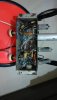
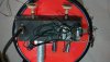
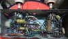
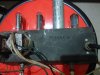
I have got this Valve Amplifier salvaged from a RCA Victor Changer console. The Turntable is fully damaged and hence, can not be used. Any Chance of using this as a standalone amplifier to be used with a Garrard Changer.

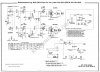
As I do not have any idea about the Valve Amplifer circuits, I am looking somebody to check the same.

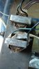
Also, I have not seen any Power Transformer in this console. Is it missing or the circuit is like this way only.

Regards,
 

Attachments

  • VA2.jpg
    VA2.jpg
    84.4 KB · Views: 61
  • VA3.jpg
    VA3.jpg
    84.7 KB · Views: 60
  • VA1.jpg
    VA1.jpg
    101.8 KB · Views: 60
Hello Suresh, nice to hear from you. The pictures are not very conclusive as a key pointer would be the valves' serial numbers - E series would mean, this is a transformer based AC unit while U-series would mean that it is a transformer-less AC/DC unit. Alternately if its a unit with E-series valves, then did you check the cabinet for a transformer mount or any evidence of a transformer's existence? I have seen some very old record players that had the power transformer and turntable motor, built into one, hence to you have any pics of the turntable? The 2 transformers look like output transformers for the 3-watt type outputs, and looks like it has 2 EL 84s or perhaps 2 ECL 82s and a ECC83 or something like that (or U-series valves with the same purpose).
 
Dear Reubin,

Thanks for the immediate response. I am attaching herewith 4 photographs of the Valve Amplifier:-

1) PIC1 - Bottom View
2) PIC2 - Top View
3) Power Cord
4) Transformer/Motor of the Changer, which is connected from amp board through a Black Wire as seen on Pic 2

The Sr. Nos mentioned on the Valves are:-

- On the 2 Valves as seen on left side of PC2 it is written as 50C5
- On one Vale as seen on the right side of PC2 it is weitten as 12AX7

The Changer was already scrapped by the person from whom I have got this module. As the Motor/transformer is connected to the amplifier board, he has removed the same and kept with the board.

Hope the above details will help you in suggesting the possibility of restoration of the amp.

Regards,
Suresh Babu
 

Attachments

  • PIC 1.jpg
    PIC 1.jpg
    71.4 KB · Views: 41
  • PIC2.jpg
    PIC2.jpg
    85.8 KB · Views: 39
  • PIC3.jpg
    PIC3.jpg
    36.7 KB · Views: 38
  • PIC4.jpg
    PIC4.jpg
    72.8 KB · Views: 41
now its pretty clear, I'll bet my last dollar on the fact that this is a simple stereo amp based on the 50C5 beam power output valve. The 12AX7 (ECC83) would have been split across both channels. Surely can be restored. The power transformer is a key element. The restoration may not cost much if your power and output transformers are functional and of course, the valves have some life remaining in them. 50C5 is used in some guitar amplifiers designs and is available at tube depot, but for around $25 a piece. The powersupply for this amp may have been mounted separately as the rectifier valve is not seem on this chassis.

Here's a sample circuit of 1 channel:

th.jpg
 
Thanks Reuben for the suggestions. I have checked again with the person from whom I have got this amp module. He is unable to recollect, whether there was a power transformer in the unit. It seems, the Power Supply Unit is missing. Please suggest a PS for this unit.

As already mentioned, as I do not have any idea about the Valve Amplifier circuits, I need help of experts in restoring the same. I will source the required parts for this restoration.

Regards,
Suresh Babu
 
Hello again, I went through the tube specs for your amp and it is clear that these tubes were designed to work in what was called at the time, an AC/DC arrangement. Usually a wire-wound rheostat type resistor was used in series with the filaments of each of the tubes. On careful examination of the pics, I see a brownish object looking like one of these. I suggest you handle this carefully as reversing the mains polarity can result in a live chassis. These are better operated using an isolation transformer.

https://en.wikipedia.org/wiki/AC/DC_receiver_design

Being a person who is into resto kind of work, its hard to gauge (if not impossible) the condition of components without properly testing them. For a start the electrolytics would need a change and these can be got locally. Not sure about the output transformers, they look to be in pretty bad shape physically but may be working, would need to be tested. Tube designs are very simple and easy to fix if you know what to do or look for, however be careful about those high voltages, especially as this is a AC/DC set. By simply reversing the mains connection, you'd get a live ground chassis.
 
Last edited:
Reuben - Many thanks for the inputs. I am interested in restoration of this amplifier - without any time frame. Suggestion now requested on "Where to Begin the Work ?".

Regards,
 
When chartering into the unknown with equipment, the first thing I would try to do is to draw out the schematic looking at how things are wired and then do research online to see if I can find something similar. One thing you'd have to do anyways is to check the components, especially those output transformers. All electrolytics would need a default change but if you have a capacitance meter, you would want to check out the paper caps as well. I would even check the resistor values as there can be cracks and breaks. The wire-wound resistor which is connected in series with the series filament wiring is another key component. If this is not working, you'd have a problem. I have found these in old radios to be extremely brittle and crack/break or power off easily. Remember, AC/DC equipment is extremely dangerous to handle so please be very careful. Reversing the mains plug can result in a live chassis, unless you get yourself an isolation transformer.
 
now its pretty clear, I'll bet my last dollar on the fact that this is a simple stereo amp based on the 50C5 beam power output valve. The 12AX7 (ECC83) would have been split across both channels. Surely can be restored. The power transformer is a key element. The restoration may not cost much if your power and output transformers are functional and of course, the valves have some life remaining in them. 50C5 is used in some guitar amplifiers designs and is available at tube depot, but for around $25 a piece. The powersupply for this amp may have been mounted separately as the rectifier valve is not seem on this chassis.

Here's a sample circuit of 1 channel:

View attachment 29400

Nice analysis Reuben. Like your DIY spirit.
 
Sureshbhai,
I was searching for some SE Tube amps and phono consoles. Your Post got me curious and I searched. I have found your model it is RCA Victor SES-3K. Your Chassis no RS-184A also matches. See this link.
https://www.radiomuseum.org/r/rca_ses_3k_ch_rs_184a.html
See if you can find schematics. I guess Centere On/off (1) Knob is missing. Since this is American Company If you wish I can post in diyAudio forum and may get better results or may be a schematics. However your transformers, Tubes etc should be working.
Regards
 
GM,
here is your Schematic. I have not seen your amplifier in detail but I believe 99 % it is the same. The picture of actual amplifier in the link and picture you have posted is same, Chassis No. is also same. However I am not an expert on circuits but I believe this will be having some special speakers (Transforemer based ?) and they would be carrying high voltages ( do not touch speaker basket). Be carefull.
Regds.
 

Attachments

  • RCA Victor Chassis 184A.jpg
    RCA Victor Chassis 184A.jpg
    870 KB · Views: 21
Last edited:
What I guess is this used to be compact phonograph where all high voltages including speaker were in side the wooden box. So chances of touching something live were minimal. But you are absolutely right about restoration. Personaly I would only restore if other components and wooden case (as per american safety standards) etc. were intact. However with schematic and most of the part the new goal should be building simple safe SE tube amp..

In the schematic there are 2 speakers per channel. I am confused about that. They are distinctly marked Spk 1, 2, 3 and 4.. Am not expert but there is no transformer and high voltages were directly supplied to tubes. Also the working of output transformer and tubes should be checked first. Lets hope Sureshbhai finds someone who can build this amp. Would be great to listen to 78s and occasionally other
Regards.
 
Yes, you are right there are indeed two speakers per channel wired in parallel. It must be part of TT RCA console with 2 drivers each side. The tweeters on vintage consoles often came with a cap already soldered on to them so the schematic probably doesn’t show them.

Though those are output trafos but I don’t know why ther are referred to as isolation transformers.
Probably the speakers had transformer and served as such . Not sure though.
Regards
 
Wharfedale Linton Heritage Speakers in Red Mahogany finish at a Special Offer Price. BUY now before the price increase.
Back
Top