2Way Bookshelf Project - 1st Project

biyer

Active Member
Joined
Jan 15, 2009
Messages
151
Points
28
Location
Pune
Hi All.

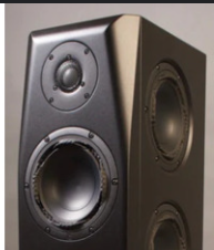
I just completed my first diy 2-way bookshelf speaker project. Please could you share your opinion and what I can do better next time.
I would like to thank FM @arunkvivek for guidance provided.
Have been looking for a project to build for some time. I got an idea after I came across the post in ASR.

The above driver is still being manufactured in India (by Peerless Audio which is currently not related to Peerless Fabrikkerne but bought over assets of peerless's Indian subsidiary)

diyaudiocart.com

Peerless SM13-PCT-8 5.25" Hi-Fi Woofer Titanium Coated PP

Peerless SM13-PCT-8 5.25" Hi-Fi Woofer Titanium Coated PP Overview: This 5.25 inch 8 ohm driver is a member of the high performance HDA (High Definiti
diyaudiocart.com
diyaudiocart.com

Then came found another tweeter from peerless which was apparently used by the Energy Connoisseur series.

https://electrocarts.in/product/25mm-silk-dome-tweeter-low-fs-neo-system/

That's how project code name Alpha/Energy was conceived.


1. I started by measuring the TS parameters myself by using test jig (https://audiojudgement.com/measure-thiele-small-parameters-using-free-software/)

Screenshot 2025-09-01 015726.png


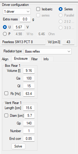
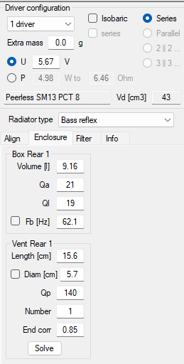
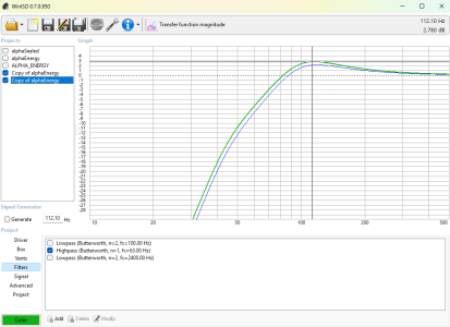
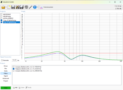
2. Then designed enclosure in WinIsd . The volume is approx. 9.14 liters with port diameter 2.25 inches, port length 6.2 inches tuned to 65hz

Enclosure was built using 18mm HDF wood which was scraps found at local CNC shop.

Dimensions are 7.5W x 10D x 13H inches.

dimensions.jpg


Screenshot 2025-09-01 011500.png


3. Measured the Drivers in box and captured FRD and ZMA. I also captured the woofer in different axis's to find cone breakup. Used Dayton imm-6 mic.
4. Used xsim to design crossover.

crossover_final.jpg


z_offset_calculation.jpg


crossover_final_estimated_response.jpg


crossover_final_impedance_curve.jpg


5. Put everything together and measured the response (All measurements are with 1/48th smoothing and 5db step size)

Screenshot 2025-09-01 012151.png


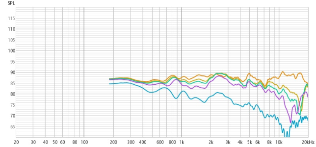
On axis 30.40.60 and 90 degree response


rew_frd.jpg


Near Field port (RED) , Woofer (BLUE) and Tweeter (GREEN)

the cabinet/ port resonance around 800hz needs to be addressed. Also need to measure with mic closer next time.

near_field.jpg


Pics
1000122081.jpg


1000119480.jpg


1000122489.jpg


Finished Painting using Granotone Speaker Paint.

1000125384.jpg


1000125383.jpg


The Total Cost of project was under 17000 INR

Overall I am very happy with the project. They sound better than my Wharfedale Diamond 9.2. I am caught up with some family responsibilities will add additional measurements once I find time.

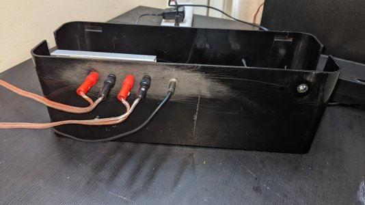
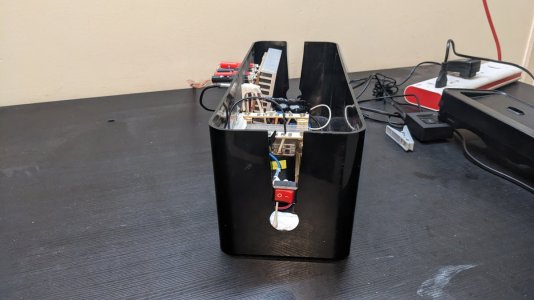
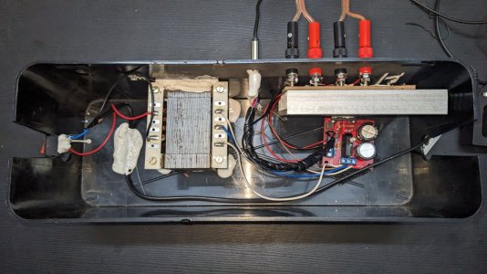
I am currently powering these using a TDA1521 board based audio amplifier which I built for testing.
 
Last edited:
Hi @biyer
For a first DIY project, you have done really good.. Congrats for that.. :)

But since you asked about what can be done better, here are some suggestions based on different aspects of the build:

1) Midbass driver bass alignment

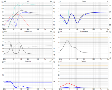
If your measured T/S parameters are accurate, this is a relatively high Qts midbass, which might like a closed alignment better than a bass reflex. This is probably evident in that 4dB hump around 100Hz in your alignment sims above, when I model the same in VituixCAD, I get similar response curves with probably not accurate assumptions on the kind of damping you have used inside cabinet

1758337880767.png


1758337745522.png

Note that you are close to running out of excursion around 40Hz with a power exceeding 5W into the woofer. Also, even though generally 4dB humps in bass sounds very nice in the beginning, it may become too much and fatiguing over time. So generally, people go for 1-2 dB bumps in the bass. Again all depends on your room situation as well. If there are room modes killing everything near 100Hz, you may/may noe percieve the differences.

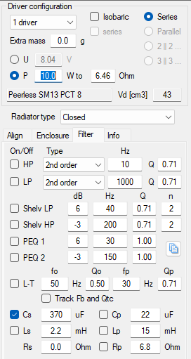
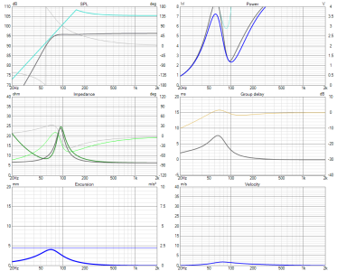
Now, if you had used a closed box alignment and used a series capacitor on the woofer of value around 370uF (good quality electrolytic caps are fine I think), you could get a much more balanced response like below and push more than 10W of power before excursion limits come into play. You can have some DC protection on the woofer as well

1758338255691.png
1758338223961.png
 

Attachments

  • 1758337786447.png
    1758337786447.png
    21.2 KB · Views: 5
2) Speaker box shape & baffle step compensation
You have not stated anything about baffle step compensation above. I assume that you have taken it into consideration.. Even if not, your bass hump and the series inductor of 2mH might play a role in flattening the response eventually. But it is always take its effect into consideration and then tune the overall response.

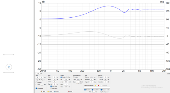
My simulations show the following profile for baffle diffraction based on your baffle dimensions. This is pretty significant and good to account for in the crossover sims
1758338702327.png


You seem to have a mild waveguide on the tweeter and a phase shield (uasually helps with the aluminium dome break-up at the top, but I dont know why they have used it if it is a silk dome tweeter). While the waveguide might help you in managing diffraction to some extent, having rounded/chamfered edges starting immediately at the tweeter edges is among the best options to terminate a waveguide on a baffle at least relatively properly. In general, shoe box shaped boxes are never the best shapes for speakers. But sometimes it is all we can do in a relatively low cost build

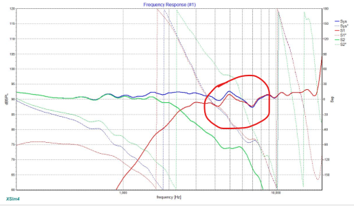
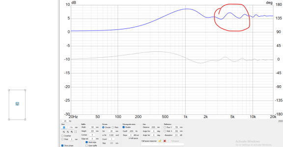
If you have been wondering where that bump in tweeter response around 4kHz is coming from, it could probably be from the diffraction response of your baffle to your tweeter. Below is an example of the diffraction sim for the tweeter based on dimensions you have given

1758339128234.png

1758339193599.png

Among the better options to use this tweeter in a baffle may be a baffle shape as shown below
1758339382974.png
 
Last edited:
3) Frequency response measurements & sound balancing via crossover

I really appreciate you take off axis measurements on a first build.
1758339459284.png

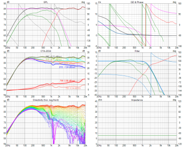
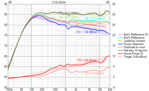
However, it does not confirm much by itself other than that there is some diffraction impact or crossover impact around 2.5kHz. I would suggest that you learn to take proper polar measurements in future and use VituixCAD fr processing. It will give you much more insight into how sound energy is radiated into 3D space. For example, here is a sample plot and the kind of information it can give
1758339719977.png

1758339737924.png

You can see the state of axial response and other associated curves such as Listening window response and power response.
The further away from the speaker you are while listening, one of these curves might become more significant in telling how much balanced the speaker response is. For nearfield listening, the axial response might dominate perception, while if you sit about 1 or 2 m away, the listening window response and power response might have their say. Accordingly, you can optimize the response in the crossover based your goals
 
Last edited:
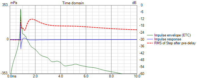
4) Monitoring the impulse response/timing aspects in crossover design

Your speaker being a small 2 way speaker has less potential to screw up timing of the speaker. But on a more elaborate build/speaker concept, it is always good to have a check on timing aspects via plots showing ETC/RMS of the step response as well, while striving for a smooth set of frequency response curves. While the ASR (audiosciencereview) crowd says spinorama is the be all, end all of speaker design, more experienced designers who have actually designed hundreds of speakers repeatedly say about the importance of not underestimating the timing aspects along with smooth frequency responses.
Here is an example set of timing-related curves for the speaker responses I posted above.
1758340392684.png

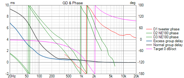
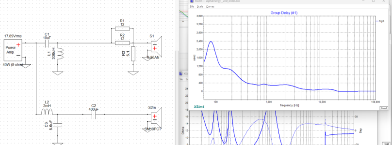
Also good to keep an eye on the excess group delay around 100Hz and trying to not exceed about 2.5ms at 100Hz
1758340751695.png

In fact, there are more discussions and examples of how good/bad timing aspects can look like
(The above thread is a treasure trove of speaker design information from one of the most experienced speaker designers I have ever known. So learn everything from it, while you are at it.. :) )
 

Attachments

  • 1758340371086.png
    1758340371086.png
    63.2 KB · Views: 5
End of the rant.. :)
Hopefully, it is useful to someone..
In general, start using the latest tools (VituixCAD at the moment, compared to XSIM & Jeff's PCD) if one might not want to be limited by the handicaps of the design tools. Learn the proper way to take measurements and use the equipment required. And then have a go at it. :)
It is 2025.. The time for single-axis frequency response optimisation-based speaker design is long gone..
 
Hi @Vineethkumar01 , Many thanks for the detailed response. Really appreciate you taking time for giving such a detailed response.
I agree with all of your points.

The TS parameter measurements are relatively accurate tested them over 5-6 driver whose ts parameters are known. Didn't get exact values but were in close ballpark to help with enclosure design.

Initially wanted to use Virtuix cad but due to commitments and to wrap up things quickly for the time being shifted to XSIM and then in future redesign if needed.

Original plan was to take off axis measurements of both drivers and then use them for crossover design in Virtuix Cad.

I started with the idea of replicating the PSB alpha B1 for the enclosure so never considered sealed enclosure. A lesson for me to not neglect other enclosure types in the future while designing. I was also looking at similar alternative drivers like


the above were touted as replacement drivers for PSB alpha B1.


1) Midbass driver bass alignment

Regarding the 4db hump I took some inspiration from LS3/5A and Diamond 9.1 , Also the extended plan was to construct a subwoofer and cross it around 80-100 hz using diy opamp based analog HPF and LPF which also takes care of cone excursion.

Read somewhere that excursion below the response spec of driver doesn't matter. But I will rather take caution and add a series Capacitor as an HPF before the woofer.

1758535689935.png

1758535737981.png

But I really liked your idea of a series Capacitor I am planning to add one, would like your opinion on which I can go.


Let me discuss point no 4 before others

4) Monitoring the impulse response/timing aspects in crossover design

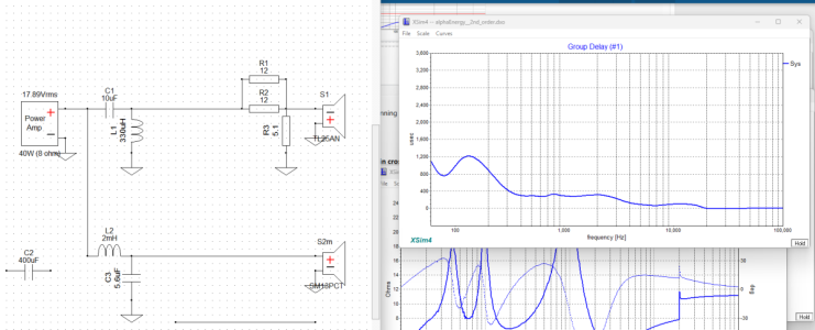
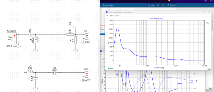
1200 usec (1.2ms ?) is group Delay value in XSIM in hte current crossover config.

1758536000081.png

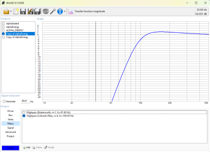
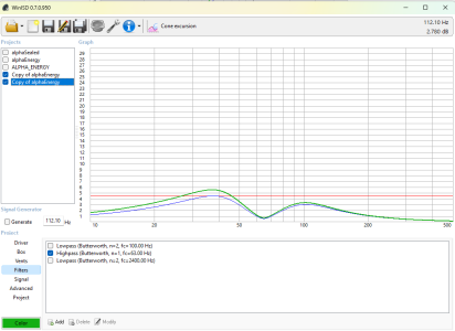
I am considering 3 options for the HPF cap before the woofer.

Option 1.

Took Nominal Impudence or Rdc as 6.5ohm.

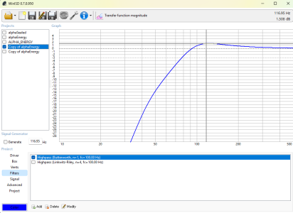
250 uF https://diyaudiocart.com/product/bevenbi-250uf-100v-electrolytic-non-polarized-crossover-capacitor/

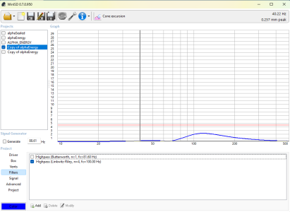
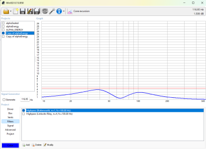
This has a cut off of around 100hz (considering ) which smoothens the response (max 1.5db) and dampens the excursion to below max of 4.5mm when provided 25W power . (max amplifier power I am aiming for but power handling should be higher due to other losses and tweeter.)


1758536455544.png

1758536516370.png

But I get a group delay of around 2900 usec (2.9 mS)

1758536707185.png


Option 2:

400 uF Capacitor with a Fc of around 63hz but dampens poorly max 2.5 db

1758536893641.png

Also cone excursion is still a little high

1758536977668.png


But group delay is improved with max 2390ish usec (2.4 ms)
1758537087902.png


Do you think its a good idea to add one?
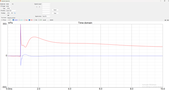
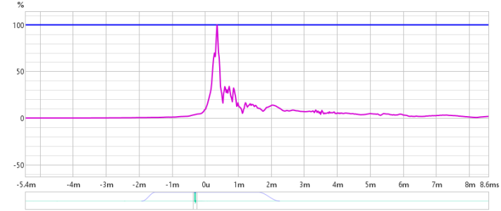
Below is the ETC


1758537330917.png


I have also found the z-offset timing using PCD which I used in XSIM.

Now onto point 3

3) Frequency response measurements & sound balancing via crossover

Yes the crossover is at 2.4Khz. I measured the off axis response so that I can create polar map etc at a later time.

Using this link as guide https://www.audiosciencereview.com/...ents-spinoramas-with-rew-and-vituixcad.21860/


2) Speaker box shape & baffle step compensation

I originally wanted to round the edges but again had to wrap up. I will try this at a later time.

For baffle step compensation I thought I can handle it with FRD measurements in crossover design software.
 

Attachments

  • 1758537064526.png
    1758537064526.png
    60.1 KB · Views: 8
Last edited:
@biyer - excellent finish. Waiting for a listening session! Dainty subwoofer next! Also post some pics of the testing amp!


Hi Arun . I have used TDA1521 based boath which provides updo 12W of power with 0.5% distortion.

The IC requires minimum external components so I thought the changes of screwing this will be minimal.

I used the below board which comes with a rectifier circuit builtin. Only think I needed the manage some grounding to handle hums. But now its silent.

Just note nobody should run an amplifier without a fuse at least after the transformer. I will add fuse later.

 
Hi Arun . I have used TDA1521 based boath which provides updo 12W of power with 0.5% distortion.

The IC requires minimum external components so I thought the changes of screwing this will be minimal.

I used the below board which comes with a rectifier circuit builtin. Only think I needed the manage some grounding to handle hums. But now its silent.

1000126386.jpg1000126385.jpg1000126384.jpg
1000126387.jpg

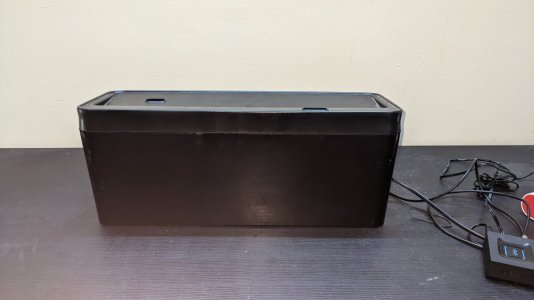
The cabinet is made of https://www.amazon.in/APPUCOCO-Cabl...pcontext&ref_=fplfs&psc=1&smid=A1HDE05ESXIWOC
 
Last edited:
Hi @biyer

Regarding the bass alignment, I was suggesting a series cap for a sealed box alignment for the midbass. Not the ported version that you have now.
With a high Qts woofer tuned with Q > 0.7, the series cap will interact with the impedance to flatten the bump and extend the response to low frequencies. It is a very old trick that has been in use from the 70s. I hear that some of the philips high Q woofer used the trick to extend bass a little bit more in a sealed box. (Here is an example scenario where this trick is being used: https://www.humblehomemadehifi.com/download/Humble Homemade Hifi_Black Box.pdf)

With the ported alignment, the high pass will just act as a high pass filter, which may be helpful with subwoofer integration but not for the above-mentioned purpose.

Regarding group delay, I think your measurement has not been centered to impulse peak in REW, hence the large group delays I think. Not sure though. Also, you need to merge nearfield and farfield response along with baffle step to get actual response
Also excess group delay measurement/graph is what you want to look at and not the group delay itself. These are available in proper places (impulse view) in VituixCAD. So, no need to use REW for it..

If you are willing, you can post your measurement REW .mdat files here and I can take a look.
 
Join WhatsApp Channel to get HiFiMART.com Offers & Deals delivered to your smartphone!
Back
Top