
Ravindra Desai
Well-Known Member
Hello all,
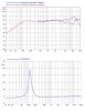
Attached is an impedance graph of a speaker that we normally do not see, yet it is the type of driver we all would like to have in our systems.
Also take a look at the frequency response that extends so nicely to the full end of the audible spectrum.
The special thing about this driver is that the impedance remains almost constant about its nominal value which is not the case, normally.
This is the type of impedance curve that you should look for, for most amplifiers.
Needless to say drivers with such impedance curve do not come cheap.
For more info and examples, look for Scanspeak drivers.
Isn't that contradictory?
A voltage source will follow Ohms law.
For the same voltage, current will be proportional to impedance. So if impedance varies, the current will also vary!
A big thing to understand, always, is that it is the current flowing through the speaker that causes the movement of the cone, not voltage.
However, you helped me make my point that almost all amplifiers in the market are voltage amplifiers.
Thanks to you all for contributing to this thread and taking it forward.
Regards,
Ravindra.
Attached is an impedance graph of a speaker that we normally do not see, yet it is the type of driver we all would like to have in our systems.
Also take a look at the frequency response that extends so nicely to the full end of the audible spectrum.
The special thing about this driver is that the impedance remains almost constant about its nominal value which is not the case, normally.
This is the type of impedance curve that you should look for, for most amplifiers.
Needless to say drivers with such impedance curve do not come cheap.
For more info and examples, look for Scanspeak drivers.
Also, an amp is a voltage source, it will swamp any impedance variation of the load, it must do it, to do it, it has low impedance in its intended bandwidth.
Isn't that contradictory?
A voltage source will follow Ohms law.
For the same voltage, current will be proportional to impedance. So if impedance varies, the current will also vary!
A big thing to understand, always, is that it is the current flowing through the speaker that causes the movement of the cone, not voltage.
However, you helped me make my point that almost all amplifiers in the market are voltage amplifiers.
Thanks to you all for contributing to this thread and taking it forward.
Regards,
Ravindra.
Attachments
Last edited:
")