Amplifiers: What causes deterioration in stereo imaging, tonal balance and dynamics

I doubt it, arj.

All tubes operate at High Voltage & Low current, while 4 & 8 ohm speakers need Low Voltage & High Current (since their impedance is is low... just 4 or 8 ohms)

The Output transformer converts the High Voltage & Low Current from the Tube To What the speaker requires.... a loose analogy would be a car gear box which provides different choices of Torque & Speed, as required.

Maybe I would change the statement to :

"Output transformers of valve amps help towards delivery of full power to a wide variety of Speaker impedances"


The output transformers have different taps for 4, 8 & 16 Ohm speakers, enabling delivery of their Full power into either 4 ohm, or 8 ohm or 16 ohm speakers.

Solid State Amps, on the other hand will ideally deliver only Half their power power (of 4 Ohms) into 8 Ohm loads and only Quarter of their power into 16 ohms speakers.

As an example, a Solid State amp will deliver:
50 Watts into 4 Ohms
or 25 Watts into 8 Ohms
or 12.5 Watts into 16 Ohms.

A Valve amp with different output transformer taps / windings will deliver
50 Watts into 4 Ohms
50 Watts into 8 ohms
50 Watts into 16 Ohms
Thanks a lot @IndianEars ( somehow still remember you as Amp_nut :D)

I do have a question in this as many SS amps seem double the power when impedance drops eg Nad M23 or pass INT25 (25W at 8 and 50 at 4.. etc) . Are they doing it in any other way ?

I understood this as amps are designed either to be a constant current source ( power is directly proportional to Load) or constant voltage source ( power inversely proportional to load) and I understood tube amps primarily being the former due to the output transformer.
 
@IndianEars: Thanks a lot for your clear explanations in above posts.
Could you also please tell us about importance of total harmonic distortion specs in amps.
Like how much does it matter and what could be a reasonable target for THD etc.

Thanks
Vineeth
 
To answer your query, arj

Solid State Power amps typically can deliver large amounts of current, directly into the loudspeaker. Hence if the Power Supply is up to it (and the output devices can sustain that heat dissipation), they will provide enough current to double the power delivered into 4 ohms compared to 8 ohms.

Valves on the other hand Must have a Transformer in between the Output Valves and the loudspeaker. The Output transformer has its own:
  • Series Resistance of the windings
  • Series Inductance of its windings
  • Limited power capability due to the the amount of Iron in the transformer core
All these factors quite severely restrict the transfer of power from the Output tubes to the speaker.
 
@IndianEars: Thanks a lot for your clear explanations in above posts.
Could you also please tell us about importance of total harmonic distortion specs in amps.
Like how much does it matter and what could be a reasonable target for THD etc.

Thanks
Vineeth
Appreciate your kind words, Vineeth.

Over the years, designers have been devising tests to measure the performance of audio amplifiers. Sadly, there have been controversies regarding the relevance of these tests, regarding their impact on sound quality.

Total Harmonic Distortion (THD) is the Grand Daddy of all these tests :) & some feel its the least relevant.....

However, THD is a convenient % figure and invaluable for the marketing folks to trumpet the amplifier they are selling.

Designers can reduce THD to vanishingly low levels... Down to PPM (Parts per Million) not just % (which is parts per hundred).

However, the tools used to reduce THD, like Negative Feedback, Feedforward etc are now considered a bigger evil than distortion !

The current approach is to have reasonably low eg 0.1% to 0.01% (not vanishingly low like ppm) achieved with minimal feedback. Such amps are today promoted for their sound quality. (I could get into why Feedback and Feedforward are looked on suspiciously, if there is an interest).

HALCRO ... An Australian amplifier manufacturer created amplifiers a Decade or more ago, with distortion of less than 10 ppm. Their technical specs WOWED the world, but some termed their sound as Sterile and lacking emotion & musicality.

More recently, Purifi Audio have launched a range of Digital Amplifiers with less than 5 ppm distortion. They are available to DIY & commercial companies. The Latest NAD Masterclass amplifiers use Purifi Modules. These amps are available at the NAD distributor in Mumbai .... I have not heard them.

To summarise, TDH is a good convenient measure, not necessarily linked to perceived sound quality... The mechanisms to achieve ultra low THD, are suspect, from a perceived sound quality perspective.
 
All these factors quite severely restrict the transfer of power from the Output tubes to the speaker.
Perhaps, the guy in the video I posted above is confusing current with watts?

Halcro - some termed their sound as Sterile and lacking emotion & musicality.
Very true. A close friend ditched his 160w Halcro mono blocks for an 8w Audio Note SET. Both of us were sitting slack-jawed, the first time we AB’ed the two.
 
Please.. please.. can you tell us more about this ? :)
Thanks again for the clarity in your explanations..
I am going to try and Explain Negative Feedback & Feedforward without complex math. Lets start with Negative Feedback.

NEGATIVE FEEDBACK
It enables even an idiot of a circuit designer to create an amplifier with Immaculate specifications !:p

Feedback.png


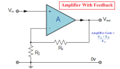
Above is a block diagram of aa amplifier using Negative Feedback.

The Blue triangle represents an amplifier. Its a Shabby designed amplifier with lots and lots of gain (eg Gain of 1 million) , but very high distortion (like 30% to 50%), High Noise, and very low bandwidth (like a frequency response of 1 Hz, yup TAT Bad).
Vin is the input voltage & Vout is the Output voltage
The Output Voltage is divided / reduced / attenuated by 2 resistors Rf & R2.

The attenuated Output voltage (Junction of Rf & R2 is fed back to an input of the amplifier and subtracted from the input. Since the feedback signal is Subtracted from the input signal, it is called Negative feedback.

The amplifier's gain without negative feedback is called its "Open Loop Gain"

With this simple routing of signal, something MIRACULOUS happens.

The (Closed Loop) gain of the circuit above is determined by Rf & R2 and can be set at anything from a gain of 1 (Unity Gain) to the open loop gain of the amplifier, if Rf is made infinite (ie removed)
Lets say the new circuit has a Closed loop Gain of 10. ie reduced from 1 million to 10 or reduced by a factor of 100,000.

The miraculous result of Negative Feedback is that the new circuit has:
  • Gain of 10 (instead of 1 million)
  • Distortion & Noise reduced by a factor of 100,000 so 50% distortion will be reduced to 0.0005% distortion.
  • Frequency response will improve from 1 Hz to 1,00,000 Hz ie 100 KHz !
Clearly all that a circuit designer using negative feedback needs to do, is design a shabby amplifier with lots and lots of gain.

Why Is Negative Feedback Bad ?
Look closely at the block diagram above.... The Signal has already reached the output, and the feedback is taken from the output and a loop created. If the signal is a very fast signal, it may be too late for the feedback to take effect and correct the output! Then, for a Very Brief moment, you will have the performance of the VERY Shoddy Open loop amplifier, with 50% distortion, etc

That is why Modern designs prefer to have a good performance open loop amplifier to beginb with, and just optimise its performance with a modest amount of feedback.

NOTE: Feedback will reduce distortion by a multiple, eg 10 time or 100 times or even 1000 times lower, but will can never make the distortion ZERO. To make the distortion ZERO, you need feedforward.


FEEDFORWARD
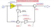
Feedforward is a completely different technique that Cancels the distortion generated by the amplifier. This is shown in the figure below:


Feedforward.png


To make the explanation easy, I have taken a 1 Volt input signal and the amplifier with a gain of 20.
I have also assumed a nasty amout of distortion: 3 Volts.
The amp output signal is fed to an attenuator or a divider, that can be simply 2 resistors.,. The attenuation is 20 ie the same as the amplifier gain. This brings the signal level back to that of the input., leaving a signal equal to the input but with the extra bit ..... the amplifier's distortion.

The Original signal is subtracted from it, leaving only the distortion, which is amplified by the second amplifier.

Finally the distortion is subtracted from the distorted amplified signal, leaving only the Amplified signal with Zero Distortion!

Again, the feedforward scheme relies on the entire signal routing being fast enough to be in time to cancel the distortion at the output. If that does not happen, you will again hear nasty sound.

Halcro amps used Feedforward to reduce distortion to vanishingly low amounts... It does not mean their circuits were perfect, thgey just used "Jugglery" to cancel the generated distortion...:D

Incidentally, Both Feedback & Feedforward were invented by the same person ....Harold Stephen Black (1898 to 1983)

He invented Feedforward in 1924 BEFORE he invented feedback in 1927.
 
I am going to try and Explain Negative Feedback & Feedforward without complex math. Lets start with Negative Feedback.

NEGATIVE FEEDBACK
It enables even an idiot of a circuit designer to create an amplifier with Immaculate specifications !:p

View attachment 66459


Above is a block diagram of aa amplifier using Negative Feedback.

The Blue triangle represents an amplifier. Its a Shabby designed amplifier with lots and lots of gain (eg Gain of 1 million) , but very high distortion (like 30% to 50%), High Noise, and very low bandwidth (like a frequency response of 1 Hz, yup TAT Bad).
Vin is the input voltage & Vout is the Output voltage
The Output Voltage is divided / reduced / attenuated by 2 resistors Rf & R2.

The attenuated Output voltage (Junction of Rf & R2 is fed back to an input of the amplifier and subtracted from the input. Since the feedback signal is Subtracted from the input signal, it is called Negative feedback.

The amplifier's gain without negative feedback is called its "Open Loop Gain"

With this simple routing of signal, something MIRACULOUS happens.

The (Closed Loop) gain of the circuit above is determined by Rf & R2 and can be set at anything from a gain of 1 (Unity Gain) to the open loop gain of the amplifier, if Rf is made infinite (ie removed)
Lets say the new circuit has a Closed loop Gain of 10. ie reduced from 1 million to 10 or reduced by a factor of 100,000.

The miraculous result of Negative Feedback is that the new circuit has:
  • Gain of 10 (instead of 1 million)
  • Distortion & Noise reduced by a factor of 100,000 so 50% distortion will be reduced to 0.0005% distortion.
  • Frequency response will improve from 1 Hz to 1,00,000 Hz ie 100 KHz !
Clearly all that a circuit designer using negative feedback needs to do, is design a shabby amplifier with lots and lots of gain.

Why Is Negative Feedback Bad ?
Look closely at the block diagram above.... The Signal has already reached the output, and the feedback is taken from the output and a loop created. If the signal is a very fast signal, it may be too late for the feedback to take effect and correct the output! Then, for a Very Brief moment, you will have the performance of the VERY Shoddy Open loop amplifier, with 50% distortion, etc

That is why Modern designs prefer to have a good performance open loop amplifier to beginb with, and just optimise its performance with a modest amount of feedback.

NOTE: Feedback will reduce distortion by a multiple, eg 10 time or 100 times or even 1000 times lower, but will can never make the distortion ZERO. To make the distortion ZERO, you need feedforward.


FEEDFORWARD
Feedforward is a completely different technique that Cancels the distortion generated by the amplifier. This is shown in the figure below:


View attachment 66460


To make the explanation easy, I have taken a 1 Volt input signal and the amplifier with a gain of 20.
I have also assumed a nasty amout of distortion: 3 Volts.
The amp output signal is fed to an attenuator or a divider, that can be simply 2 resistors.,. The attenuation is 20 ie the same as the amplifier gain. This brings the signal level back to that of the input., leaving a signal equal to the input but with the extra bit ..... the amplifier's distortion.

The Original signal is subtracted from it, leaving only the distortion, which is amplified by the second amplifier.

Finally the distortion is subtracted from the distorted amplified signal, leaving only the Amplified signal with Zero Distortion!

Again, the feedforward scheme relies on the entire signal routing being fast enough to be in time to cancel the distortion at the output. If that does not happen, you will again hear nasty sound.

Halcro amps used Feedforward to reduce distortion to vanishingly low amounts... It does not mean their circuits were perfect, thgey just used "Jugglery" to cancel the generated distortion...:D

Incidentally, Both Feedback & Feedforward were invented by the same person ....Harold Stephen Black (1898 to 1983)

He invented Feedforward in 1924 BEFORE he invented feedback in 1927.
Thanks a lot for this detailed explanation and that too with diagrams. Really appreciate the effort.
I think I got the general idea from your explanations.. :)

(I may be wrong but I just noticed a very very small thing (not even relevant to the general discussion) in the second diagram that we might have missed an inversion somewhere in the signal path.:D
This is because the yellow colored amplifier's output when subtracted from the original signal coming from amplifier input (at the first adder block) leaves a polarity inversed version of distortion, which if not inverted somewhere subsequently will again become polarity inversed at the second adder and add to the signal. I think it is also possible to correct this if we interchange the '+' and '-' signs at the first adder block. )
 
Join WhatsApp group to get HiFiMART.com Offers & Deals delivered to your smartphone!
Back
Top