Building a Plinth for Lenco L75

Regarding wobble how was the platter held on lathe and how was the center hole made ? Once put on lathe it should be finalized on lathe itself. Would give more accuracy. Also longer the bearing spindle more accuracy is required a slight variation at the end would magnify wobble.

I wouldn't know how it was clamped on the lathe as I was not present when it was done.

I measured the thickness of the platter and found that it varies. I am assuming that the acrylic from the factory would have uniform thickness. I still think the buffing is what caused the unevenness. I am not sure if this can be corrected. I am hoping it is possible, as acrylic of that thickness is super costly. I am OK to lose one or two mm more if further buffing can achieve uniform thickness.


Regarding lubricants, one theory of viscous lubricant is; 'if' motor plus idler has sufficient torque it overrides the dynamically changing stylus drag because motor is already working on little heavier resistive force of the viscous lubricant when in motion.

I do like the denser sound produced by a more viscous lube. But it shouldn't be too dense as to reduce the torque (as unscientifically measured by "anti-static brush test" described earlier).

FWIW, I bought genuine Singer sewing machine oil from faraway Dadar. The current sewing machine oil I have is a no-name one. May be Singer will be different/better.

Also, fellow forumer Rikhav is arranging a small quantity of Mobil Delvac 1 synthetic oil for me:thumbsup: I will try that as well. Thanks, Rikhav:). This is a high-performance lubricant for diesel engines, with recommended changing interval of 100,000 kms! This is supposedly thinner than the equivalent lube for petrol engines. And I am looking for something thinner than the compressor oil that I am using now.


You have achieved admirable high quality DIY, so kudos to the work well done. :thumbsup:

Thank you :)
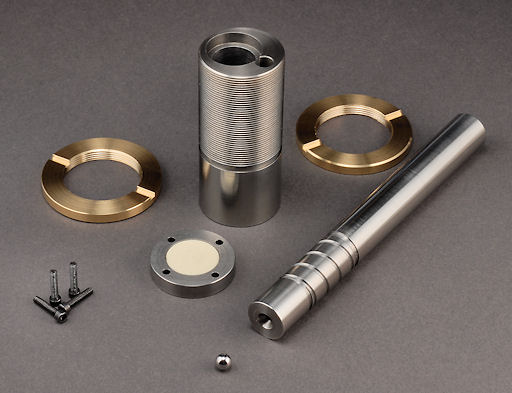
. I drilled - again and again - into the lathe machinist's head the importance of tight tolerance. For example, the spindle diameter is 7.15 mm and the hole on the platter is 7.25 mm. That's 0.1 mm tolerance. This guy didn't even bat an eyelid. He just achieved it!

The finishing is a bonus of the buffing process. I was also pleasantly surprised by the level of fit and finish.
 
The ungainly wobble is now cured!

It turned out that the acrylic sheet is uneven from the factory itself. What was supposed to be 50 mm varied from 46.xx mm to 50 mm. So I paid another visit to the lathe guy, armed with videos I captured on my phone to show him the wobble. He was quite understanding - he'd done reworkings due to uneven thickness of acrylic sheets.

He re-faced both surfaces, shaving off nearly 4 mm, followed by buffing that made the final thickness to 46 mm. Now it spins with absolutely no wobble. It is much easier on the eye than before. I have compensated the 4 mm lost by using an acrylic mat of 4 mm thickness between the stock platter and the thick acrylic platter.

Also, I have drained the compressor oil. In its place Mobil Delvac 1 5W30 synthetic engine oil for diesel engines is being tried out.

I also had the opportunity to closely examine the thrust plate. I don't see any further increase in the depth of the indentation made by the bearing ball. Also, the oil accumulated at the bottom is clean (golden yellow). There is no grit, meaning there is hardly any wear. But the sidewalls seemed a bit dry for my liking. Need to figure how to lube the sidewalls better.

Right now I'm spinning the first side of an LP after the above changes. I cranked up the volume a few notches (4 dB). Somehow I want to listen louder, as my normal listening volume seemed low today. It is sounding very good and not stressing my ears despite the extra volume.
 
I discovered something interesting, a major flaw in the way I have checked for torque. To begin with, it is obviously unscientific to use a record cleaning brush pressed down on a spinning record to see how much the brush slows down the record from spinning.

What I saw last night was when pressing the brush down for a regular cleaning of the record, it slowed down the record, BUT the thick acrylic platter continued spinning like nothing has happened. This meant that the record and the 4 mm acrylic mat below it were losing their coupling to the rest of the platter assembly. I didn't realise that it was that easy to upset the purchase (or traction, if one can call that) of the acrylic mat.

I immediately replaced the acrylic mat with a (thinner) felt mat and I could see that there is no more slippage.

Acrylic mat has its own advantage as a mat (I feel it brings out details a bit better than regular rubber mats). Perhaps the acrylic mat could be used with a record center weight. Or glued in some way to the platter for better coupling.
 
There is no grit, meaning there is hardly any wear. But the sidewalls seemed a bit dry for my liking. Need to figure how to lube the sidewalls better.
You probably know this. But if the lathe guy can manage without changing the measurements of the spindle shaft you can make spiral groove to constantly lubricate the side walls. BUT burring may occur, so be extra careful.
110605_4994_ttbearingparts1_web.jpg

Also housing holding the shaft needs to be made new to make direct hole connecting to the bottom reservoir, so when oil comes up it drains to the bottom through this hole as shown in the pic.
Regards.

That's a really well-made bearing. And offset, too, including the positioning of the thrust. Very clever indeed.

I thought about using the Archimedean screw/groove. It shouldn't be a problem machining it. It works and has been used by many bearing designers. Burring can be removed at buffing stage. But the return hole could pose a real challenge as it is going to be deep and narrow hole.

I have in mind a few improvements for a "version 2", subject to my ability to find sintered bronze bushings of the right inner and outer dimensions.

BTW, I opened the bearing assembly two days ago. Contrary to my fear, the sleeve/sidewall was fairly well lubricated. My solution to the problem for now is to pour in just the right amount of oil so as to have a constant bath even on the sidewalls. I poured in some more oil, but I honestly don't know if it's sufficient. I need to get a syringe or ink dropper to be able to top up precise amounts of oil. Also, a felt washer to prevent oil from flowing off from the top of the spindle, has to be made.

This bearing is a definite improvement on the stock bearing. I would attribute that to the fact that tolerances are very tight and allows absolutely no lateral play. This results in a lowered noise floor, which is a good thing and a bad thing. And you can tune the sonics by using different oils:)
 
Another clever turntable bearing was from Sugden. It had triangle shaped three contact point nylon pad housing holding center metal spindle shaft. A single screw was used to tighten these pads on the shaft. This helped in tightening the bearing housing on the shaft as much as one likes. Advantages of this design was least amount of contact area and nylon somewhat had a lower noise than metal to metal.
I opened the bearing assembly two days ago. Contrary to my fear, the sleeve/sidewall was fairly well lubricated.
Thats very good. you have designed a good bearing. Your bearing housing stays little above the spindle shaft (Its not flush) so after fitting you can put few extra drops on top which will ultimately lubricate sidewalls.
Regards.
 
Your bearing housing stays little above the spindle shaft (Its not flush) so after fitting you can put few extra drops on top which will ultimately lubricate sidewalls.

I am afraid it is the other way round. This is because I designed it for a bearing ball of 5 mm diameter but eventually ended up using a 6.32 mm ball as the stock 5 mm ball is rather worn. So the spindle is about (1.32/2 = 0.66 mm) above the housing/bushing.
 
Some pictures:

1) the stock L75 bearing is the one in the background, and is dwarfed by the new bearing. The second image from the foreground is the spindle meant for single platter operation. The one in the foreground is for stacked platter operation. Platter thickness upto 2 and 1/2 inches can be accommodated. VTA adjustment needs to be taken care according to the height of the platter.


2) below is the thrust "plate" with oil (actually a mix of a small amount of lithium based grease and compressor oil). Note that the oil retains its golden yellow hue after many days of usage. Notice also the tiny dimple in the center where the spindle rests.


3) side by side


4) the plan


If any one is interested to DIY this bearing for personal use, please PM me for the detailed drawing.
 
Update: I brought home my second L75 yesterday (courtesy fellow forumer Mr. Shafic). No immediate plans to start rebuilding it, however. Not that they're any different, but this one is "Lenco L75" whereas my older one is Goldring badged "GL75". The arm is bent at a funny angle but works! It doesn't matters to me as I won't be using the arm anyway. Cosmetically, it is in acceptable state.
 
Update: I brought home my second L75 yesterday (courtesy fellow forumer Mr. Shafic). No immediate plans to start rebuilding it, however. Not that they're any different, but this one is "Lenco L75" whereas my older one is Goldring badged "GL75". The arm is bent at a funny angle but works! It doesn't matters to me as I won't be using the arm anyway. Cosmetically, it is in acceptable state.

Congratulations !!

Both are the same. just that in UK lenco did not directly sell there but via Goldring hence rebadged as Goldring Lenco (GL)

Similarly in the US it was Bogen Lenco. but if you check the parts they were all made and sourced from the same factories. i think the motor is swiss, the platter Italian etc etc !
 
Last edited:
Update: I brought home my second L75 yesterday (courtesy fellow forumer Mr. Shafic). No immediate plans to start rebuilding it, however. Not that they're any different, but this one is "Lenco L75" whereas my older one is Goldring badged "GL75". The arm is bent at a funny angle but works! It doesn't matters to me as I won't be using the arm anyway. Cosmetically, it is in acceptable state.

Congratulations on this Joshua and cheers to Shafic :)

Pictures please....
 
An useful tool for calculating the rpm of your TT (for Android)

Edit: a caveat - I just installed it on my phone. It shows 0.3 rpm and my phone is stationary:lol: which is about 0.9% error. May be there is some way of calibrating it. I will try to figure it out.
 
Last edited:
Amazing. Have you tried it? Does it work any better than the simple rotating pattern under a light test? I suppose that the answer is yes, it tells the actual speed, not just wrong or right.

Oh... :eek: Does the phone get dizzy?

Talking about phone apps and turntables, how many people use a spirit-level app for levelling their turntables? Accurate enough?
 
I completely forgot to try out the RPM Calculator app. So I tried it last night. It showed my Lenco L75's rpm as 32.x rpm when set to play 33.3 rpm, the "x" varying quite a bit and not stabilising to a fixed number. So I adjusted the speed to 33.x rpm. Even there it did not settle to a particular decimal figure but the "x" kept varying from 0.2 to 0.6 or even 0.8. To cross check, I used a strobe disc and it disagreed. So I ended up re-adjusting the speed as per the strobe disc. After adjusting it, the RPM Calculator showed 32.x again.

I tried the app on a second turntable and it showed 32.x again where as the strobe disc was nearly stationary at 33.3.

So I am guessing there is a fairly large negative error in the reading of the RPM Calculator. Any one knows a better app for Android?
 
I would trust a proper strobe disk. ...

Originally, these "rotating" speed indicator disks were made to work with an ordinary incandescent bulb*, utilising the known AC frequency.

Nothing more complex required. Or is it? Or is the simple version something that is more reliable in countries where the mains supply is more reliable. Some of us are all to aware of wildly fluctuating voltage: does the frequency fluctuate too?


*I learnt on this forum that fluorescent/CFL lamps, due to their own electronics, do not pulse at the same frequency.

~
 
Last edited:
Wharfedale Linton Heritage Speakers in Walnut finish at a Special Offer Price. BUY now before the price increase.
Back
Top