You are using an out of date browser. It may not display this or other websites correctly.
You should upgrade or use an alternative browser.
You should upgrade or use an alternative browser.
HMV Fiesta Popular Mono Record Player Circuit Diagram
- Thread starter sureshkuranjalayil
- Start date

A K Bhattacharjee
Active Member
Contact Saket. He might have the circuit diagram. As I remember he helped a fm before.
sureshkuranjalayil
Active Member
Thanks.Contact Saket. He might have the circuit diagram. As I remember he helped a fm before.
Hi,
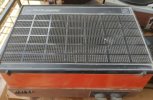
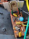
I am restoring my first HMV Fiesta Record Player which was lying unused for more than 10 years now. The Platter is rotating at correct speeds but Amplifier Section is not working. It is only generating a "Hum" while playing. Attached is the photograph of the Amplifier Board. Suggestions requested from members how to proceed with repairing of this board.
Thanks in advance.
Regards,
Suresh Babu
Attachments
reubensm
Well-Known Member
Why would you require a schematic to fix this? The schematic is already on the PCB ")
Also assume that 'hum while playing' means no music can be heard, only a low deep hum which does not increase or decrease when turning the volume control. Also assume that all connections are originally connected and have not been disconnected or nothing was in disconnected state (for example, reversing the polarity of the PSU to the amp board can also cause a low hum)
Its a simple AC127/128 (or perhaps AC187/AC188) amplifier driven by either a AC127 or AC128 driver transistor (cant make out the connections on the PCB or I could have told you which one) and a silicon BC148B perhaps (or 147 or 149) as the front end. There is literally nothing that can blow on this PCB except for the 4 transistors and that output coupling capacitor (electrolytic) to which the speaker is wired. Assuming the PSU board (not shown in the pic) is great with good filter capacitors and diodes, then all you would need to do is to check the transistors and that output capacitor. Start with the PSU and check the voltage output (should get DC, if the rectifier diodes are short circuiting then you'd get AC). Then check the transistors on the amp board. These old germaniums tend to have a problem which is, they turn leaky over a period of time and malfunction or their legs start to rust and break off inside the can. Knowledge of basic electronics and knowing how to use a multimeter to check npn and pnp transistors and PSU voltages, will be required for this task.
Note: while checking germanium transistors (AC127/AC187-npn, AC128/AC188-pnp), always check for readings between the collector and emitter in both directions, if you obtain resistance in one direction or both, he transistor is likely to be leaky. Also base to emitter and base to collector readings should show resistance and not a direct short. Also check for readings in with opposite polarity as well, which should be null. If this sounds complicated, there are many videos on youtube on how to test pnp and npn transistors.
Last edited:
sureshkuranjalayil
Active Member
Thanks a lot.Why would you require a schematic to fix this? The schematic is already on the PCB
Also assume that 'hum while playing' means no music can be heard, only a low deep hum which does not increase or decrease when turning the volume control. Also assume that all connections are originally connected and have not been disconnected or nothing was in disconnected state (for example, reversing the polarity of the PSU to the amp board can also cause a low hum)
Its a simple AC127/128 (or perhaps AC187/AC188) amplifier driven by either a AC127 or AC128 driver transistor (cant make out the connections on the PCB or I could have told you which one) and a silicon BC148B perhaps (or 147 or 149) as the front end. There is literally nothing that can blow on this PCB except for the 4 transistors and that output coupling capacitor (electrolytic) to which the speaker is wired. Assuming the PSU board (not shown in the pic) is great with good filter capacitors and diodes, then all you would need to do is to check the transistors and that output capacitor. Start with the PSU and check the voltage output (should get DC, if the rectifier diodes are short circuiting then you'd get AC). Then check the transistors on the amp board. These old germaniums tend to have a problem which is, they turn leaky over a period of time and malfunction or their legs start to rust and break off inside the can. Knowledge of basic electronics and knowing how to use a TTh
As you said, the low deep hum, which is not increasing or decreasing. I have gone the internals and it is noticed that All the connections are intact.
Checked the power supply board and the output DC Voltage is 9.34. Hence, presuming that the power supply is working fine.
Now I will check the Transistors and update here.
Regares,
Suresh
reubensm
Well-Known Member
low deep hum is a sign that one or both the output transistors or the driver transistor is shorting
a 9volt powersupply suggests that this is a 1 watt amplifier
a 9volt powersupply suggests that this is a 1 watt amplifier
sashijoseph
Member
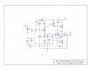
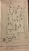
For what it's worth,here's the schematic formalised from a rough paper sketch done sometime back.Hello,
If anybody is having the Amplifier Circuit Diagram of this HMV Fiesta Player, kindly share the same.
Thanks,
Suresh
Hope you get the amp working.
Attachments
sureshkuranjalayil
Active Member
Thanks a a lot to Reuben & Shashi Joseph for the valuable inputs.
On checking, both the Transistors AC 127 & AC 128 are not working. Seems it is very difficult to get the same.
Any pointers to get these transistors will be highly appreciated. If these are not available, please suggest any other circuit with presently available components so that same can be retrofitted in the player.
Regards,
Suresh
reubensm
Well-Known Member
FM Dr.Partha had a similar requirement some time ago and was able to source these transistors. I think a consulting with old time radio shop owners or technicians will help you source these. Getting new ones in India is impossible, you'd have to get transistors salvaged from old PCBs. If price points arent a problem then these can be easily procured from ebay.de or from aliexpress.com
I can give you some pointers of equipment from which you are likely to find these:
1) old philips transistor radios, cassette recorders and 2 in ones, especially the imported ones of the 70s (the pre-IC era). The key here is to keep an eye for the FM band. The reason is simple, FM band means higher quality and that would mean, the low power amp would not likely be using driver and output transformers (if you look in transistor radios that use driver and output transformers, you will find AC128 but not AC127)
2) old low power transistor amplifiers, employed transistors like AC187 AC188 SL100 SK100, etc as in pre-driver and driver stages in the, any of these discarded ones may lead you to these transistors
3) old portable reel tape recorders, especially the Japanese ones by National, etc that were carried around by journalists in those times
4) regulated small powersupplies in the 70s commonly used AC127/128 transistors
5) certain old Ahuja amplifier models like the SSB60 and SSA125 used transistors like AC127 and AC132 (direct substitute to AC128) in their power amp stages. An older Ahuja service center or a visit to a scrap yard will help you locate these amplifiers. The SSB60 was quite popular in the 1970s and early 1980s, especially in schools so there are tones of them out there.
When it comes to these small record players, it is always good to have the original circuit installed as you can return the item to its original sounding state. However if you really must replace the board, any 1 watt amplifier, with a single transistor phonostage will be superb. I have used TBA 810 IC based amps running at 9v for similar applications.
sureshkuranjalayil
Active Member
Thanks Reuben for the valuable and detailed explanation.
Under point No.2, you have mentioned about AC 187 & AC 188 Transistors. I have got a Stereo Amplifier board of HMV Record player. 2 Nos. each of AC 187 and AC 188 transistors are seen on this board. If these are working, can I replace AC 187 & 188 in place of AC 127 & 128 respectively.
Regards,
Suresh
reubensm
Well-Known Member
yes, AC187 and AC188 can he used as direct replacements for AC127 and AC128. The AC187/188 pair will deliver 1 watt with a 9 volt power supply. Personally I have found the sound quality of the AC187/188 pair to be better than the 127/128 pair. Don't forget to slip on the heat sinks and if there is a thermistor, that should be in contact with the heat sink. or as in the existing installation.Thanks Reuben for the valuable and detailed explanation.
Under point No.2, you have mentioned about AC 187 & AC 188 Transistors. I have got a Stereo Amplifier board of HMV Record player. 2 Nos. each of AC 187 and AC 188 transistors are seen on this board. If these are working, can I replace AC 187 & 188 in place of AC 127 & 128 respectively.
Regards,
Suresh
In my junior school days, I had constructed a 4-transistor 1 watt amplifier with AC127/128 as output transistors and AC128 and AC127 in the driver and pre-driver stages, running on a 9v battery pack. Dad suggested that I swap all 4 with AC187/188 and when I did so, the amplifier sounded much better and louder
I still have that amplifier board. All the very best.
Last edited:
sureshkuranjalayil
Active Member
Thanks. Unfortunately, I have got only one AC 187 Transistor from the board lying with me. One of my friend informed that he is having few AC 127/128 with him. Will get get the same once the lockdown period is over.yes, AC187 and AC188 can he used as direct replacements for AC127 and AC128. The AC187/188 pair will deliver 1 watt with a 9 volt power supply. Personally I have found the sound quality of the AC187/188 pair to be better than the 127/128 pair. Don't forget to slip on the heat sinks and if there is a thermistor, that should be in contact with the heat sink. or as in the existing installation.
In my junior school days, I had constructed a 4-transistor 1 watt amplifier with AC127/128 as output transistors and AC128 and AC127 in the driver and pre-driver stages, running on a 9v battery pack. Dad suggested that I swap all 4 with AC187/188 and when I did so, the amplifier sounded much better and louder
Regards
reubensm
Well-Known Member
AC127/AC187 is the harder one to get
sureshkuranjalayil
Active Member
Thanks a lot.Hi Suresh,
i hope you received the diagram that I sent you over mail. Attaching again here for reference.
Regards,
Saket.
Hello!FM Dr.Partha had a similar requirement some time ago and was able to source these transistors. I think a consulting with old time radio shop owners or technicians will help you source these. Getting new ones in India is impossible, you'd have to get transistors salvaged from old PCBs. If price points arent a problem then these can be easily procured from ebay.de or from aliexpress.com
I can give you some pointers of equipment from which you are likely to find these:
1) old philips transistor radios, cassette recorders and 2 in ones, especially the imported ones of the 70s (the pre-IC era). The key here is to keep an eye for the FM band. The reason is simple, FM band means higher quality and that would mean, the low power amp would not likely be using driver and output transformers (if you look in transistor radios that use driver and output transformers, you will find AC128 but not AC127)
2) old low power transistor amplifiers, employed transistors like AC187 AC188 SL100 SK100, etc as in pre-driver and driver stages in the, any of these discarded ones may lead you to these transistors
3) old portable reel tape recorders, especially the Japanese ones by National, etc that were carried around by journalists in those times
4) regulated small powersupplies in the 70s commonly used AC127/128 transistors
5) certain old Ahuja amplifier models like the SSB60 and SSA125 used transistors like AC127 and AC132 (direct substitute to AC128) in their power amp stages. An older Ahuja service center or a visit to a scrap yard will help you locate these amplifiers. The SSB60 was quite popular in the 1970s and early 1980s, especially in schools so there are tones of them out there.
When it comes to these small record players, it is always good to have the original circuit installed as you can return the item to its original sounding state. However if you really must replace the board, any 1 watt amplifier, with a single transistor phonostage will be superb. I have used TBA 810 IC based amps running at 9v for similar applications.
Hope you are doing well.
Yes, I've found these Ge pair after much searching. They are hard to find but can be found in old shops as you have advised me previously. It helped me a lot to restore that HMV Fiesta which bears an emotional value.
Thanks for your help.
I have a question in this aspect. I have a few of these GE pairs. All of these transistors are showing collector to emitter resistance of 124-125 ohms. This means they are leaking? But when I put them in the circuit, they serve their purpose. Does this mean they are going to end their life soon?Why would you require a schematic to fix this? The schematic is already on the PCB
Also assume that 'hum while playing' means no music can be heard, only a low deep hum which does not increase or decrease when turning the volume control. Also assume that all connections are originally connected and have not been disconnected or nothing was in disconnected state (for example, reversing the polarity of the PSU to the amp board can also cause a low hum)
Its a simple AC127/128 (or perhaps AC187/AC188) amplifier driven by either a AC127 or AC128 driver transistor (cant make out the connections on the PCB or I could have told you which one) and a silicon BC148B perhaps (or 147 or 149) as the front end. There is literally nothing that can blow on this PCB except for the 4 transistors and that output coupling capacitor (electrolytic) to which the speaker is wired. Assuming the PSU board (not shown in the pic) is great with good filter capacitors and diodes, then all you would need to do is to check the transistors and that output capacitor. Start with the PSU and check the voltage output (should get DC, if the rectifier diodes are short circuiting then you'd get AC). Then check the transistors on the amp board. These old germaniums tend to have a problem which is, they turn leaky over a period of time and malfunction or their legs start to rust and break off inside the can. Knowledge of basic electronics and knowing how to use a multimeter to check npn and pnp transistors and PSU voltages, will be required for this task.
Note: while checking germanium transistors (AC127/AC187-npn, AC128/AC188-pnp), always check for readings between the collector and emitter in both directions, if you obtain resistance in one direction or both, he transistor is likely to be leaky. Also base to emitter and base to collector readings should show resistance and not a direct short. Also check for readings in with opposite polarity as well, which should be null. If this sounds complicated, there are many videos on youtube on how to test pnp and npn transistors.
reubensm
Well-Known Member
Note: this post is based on transistors that were removed from the board tested outside the circuit. When testing transistors in a circuit, surrounding components may/will influence the eventual readings and observations.
Based on my amplifier build adventures from my childhood (I don't work on these any more obviously, so its been a while), building my own SS amplifier with AC187/AC188 pair and using a traditional all germanium design with AC187/AC188 driver and pre-driver stages, AC125, AC126 preamp stages.
You'd not find these observations written anywhere and i have not bothered to go into the technical details, hence please view these as solely based on my practical experiments with germanium transistors.
I had noticed, when the transistor is new (yes, dad got me into the habit of checking these at the shop before buying), we'd get zero resistance between the collector and emitter (in both polarity directions). I had the habit of mixing and matching transistors to observe the difference in performance. Again, i had the habit of testing every transistor with a multimeter before putting them in the circuit.
I noticed that as the germaniums get older, a resistance starts forming between the collector and emitter. My father used to remove these specific transistors from his own experiments and give them to me, for my adventures, saying they have started getting leaky. What i noticed was that the leaky ones that were newer, exhibited higher resistance between the collector and emitter and with older ones, the resistance used to drop (in both polarity directions). I noted that the leaky ones with high resistance in the range of 1k or higher would work normally but as the resistance started to fall, performance issues started creeping in.
Those where times when dad would not let us use 'battery eliminators' so i had a battery box with 6 x AA batteries giving me a 9volt supply to work with. Dad put me on a ration of 2 new batteries every month and I used to rotate my battery stock and survive. I noticed that when I used output transistors with c-e resistance below 1k, it used to drain my batteries quicker and if the resistance fell below 500 ohms, the output transistors used to get hot while playing and the battery drain increased even more. If the c-e resistance went below 200 ohms, the output volume reduced and distortion started creeping in. I had a design wherein the emitters of the output transistors were directly coupled. Thinking that this was the problem, i introduced the standard 1 ohm resistors between the 2 emitters, with no success. I figured out that my amplifier worked and sounded really good when i had new output transistors with zero c-e resistance. The batteries also used to last much longer.
I had similar experiences with germanium transistors in the pre-driver and driver stages. Leaky pre-driver and driver transistors made biasing very difficult, and my output transistors used to get very hot, despite having thermistor based temperature control. I had problems with distortion as well. This was when the c-e resistance fell below 500 ohms. Again, the battery consumption increased with leaky pre-driver and driver transistors that were leaky. Interestingly the leaky transistors with resistance over 500 ohms seemed to manage ok with a little loss in amplifier gain and a different bias preset setting.
With the preamp stages, using AC125 and AC126, I had issues with low gain and distortion when using transistors with c-e resistance around or below the 500 ohm range. Again the battery consumption was affected but I figured out a way to keep these going for some more time. Essentially what I would do is to play around with the biasing and stabilizing circuit to reach a proper operating point Another key factor was the emitter bias by-pass capacitor. I used to change the value of this capacitor by hit-and-miss to arrive at a nice sounding point. But I would eventually revert back to standard values and just put back my new transistors. Fun times with these adventures.
To answer your question specifically, over time in germanium transistors, i have noticed with c-e resistance to evolve and keep dropping until a point where the c-e resistance is too low (as good as a short) for the transistor to function. That when the transistor is deemed dead. So with your transistors, they may still work but will keep doing down hill (even if not used). Older metal cap germaniums were notorious for getting leaky over time and their casing and legs would get corroded. We could clean the exposed part of the leg from time to time but what happens inside the sealed housing was beyond our control. These are factors that also contributed to the end of the germanium transistor era.
Hope this helps.
Edit: i had some OC71/72 transistors in those times (equivalent of AC127/AC128) and some OC44 ones as well (salvaged from old philips radios). All these eventually became leaky and c-e finally began to short (despite not being in use). I had to throw these away.

Based on my amplifier build adventures from my childhood (I don't work on these any more obviously, so its been a while), building my own SS amplifier with AC187/AC188 pair and using a traditional all germanium design with AC187/AC188 driver and pre-driver stages, AC125, AC126 preamp stages.
You'd not find these observations written anywhere and i have not bothered to go into the technical details, hence please view these as solely based on my practical experiments with germanium transistors.
I had noticed, when the transistor is new (yes, dad got me into the habit of checking these at the shop before buying), we'd get zero resistance between the collector and emitter (in both polarity directions). I had the habit of mixing and matching transistors to observe the difference in performance. Again, i had the habit of testing every transistor with a multimeter before putting them in the circuit.
I noticed that as the germaniums get older, a resistance starts forming between the collector and emitter. My father used to remove these specific transistors from his own experiments and give them to me, for my adventures, saying they have started getting leaky. What i noticed was that the leaky ones that were newer, exhibited higher resistance between the collector and emitter and with older ones, the resistance used to drop (in both polarity directions). I noted that the leaky ones with high resistance in the range of 1k or higher would work normally but as the resistance started to fall, performance issues started creeping in.
Those where times when dad would not let us use 'battery eliminators' so i had a battery box with 6 x AA batteries giving me a 9volt supply to work with. Dad put me on a ration of 2 new batteries every month and I used to rotate my battery stock and survive
. I noticed that when I used output transistors with c-e resistance below 1k, it used to drain my batteries quicker and if the resistance fell below 500 ohms, the output transistors used to get hot while playing and the battery drain increased even more. If the c-e resistance went below 200 ohms, the output volume reduced and distortion started creeping in. I had a design wherein the emitters of the output transistors were directly coupled. Thinking that this was the problem, i introduced the standard 1 ohm resistors between the 2 emitters, with no success. I figured out that my amplifier worked and sounded really good when i had new output transistors with zero c-e resistance. The batteries also used to last much longer.I had similar experiences with germanium transistors in the pre-driver and driver stages. Leaky pre-driver and driver transistors made biasing very difficult, and my output transistors used to get very hot, despite having thermistor based temperature control. I had problems with distortion as well. This was when the c-e resistance fell below 500 ohms. Again, the battery consumption increased with leaky pre-driver and driver transistors that were leaky. Interestingly the leaky transistors with resistance over 500 ohms seemed to manage ok with a little loss in amplifier gain and a different bias preset setting.
With the preamp stages, using AC125 and AC126, I had issues with low gain and distortion when using transistors with c-e resistance around or below the 500 ohm range. Again the battery consumption was affected but I figured out a way to keep these going for some more time. Essentially what I would do is to play around with the biasing and stabilizing circuit to reach a proper operating point Another key factor was the emitter bias by-pass capacitor. I used to change the value of this capacitor by hit-and-miss to arrive at a nice sounding point. But I would eventually revert back to standard values and just put back my new transistors. Fun times with these adventures.
To answer your question specifically, over time in germanium transistors, i have noticed with c-e resistance to evolve and keep dropping until a point where the c-e resistance is too low (as good as a short) for the transistor to function. That when the transistor is deemed dead. So with your transistors, they may still work but will keep doing down hill (even if not used). Older metal cap germaniums were notorious for getting leaky over time and their casing and legs would get corroded. We could clean the exposed part of the leg from time to time but what happens inside the sealed housing was beyond our control. These are factors that also contributed to the end of the germanium transistor era.
Hope this helps.
Edit: i had some OC71/72 transistors in those times (equivalent of AC127/AC128) and some OC44 ones as well (salvaged from old philips radios). All these eventually became leaky and c-e finally began to short (despite not being in use). I had to throw these away.
Last edited:
I'm really thankful to you as always you have helped with your huge experience. And obviously I can understand the values of those good old days where you had used batteries of 9v for experiments.
This information is self-explanatory and a layman in electronics can understand. But the sad part,what I could understand, is that these Ge pairs are going to end one day soon and I'm going to loose those feelings of warm reproductions by AC187/188 or PT4/PT6. But unfortunately, nothing to do at my part.
However, I can call it my "good luck" that at least I have grown up upto this age along with the warm sounds reproduced by Ge pairs . And it's now 40 years ! Not at all bad indeed!
Many people advised me (correctly) to switch to a better amp, preamp and vintage turntables with mag cart and not to spend money and time for those old, good for nothing germeniums. Yes. I also have those vintages (a few obviously). But what they probably missed is the "sentiments" which are all over in these players. As you have just shared (and shared in many threads elsewhere) your childhood experience, you can probably realize the sentiments attached with these cheap ceramic cart enabled players which I give immense values.
BTW, became bit emotional!
Lastly thanks once again and thanks to everybody. I'll continue to seek your help when needed.
Regards,
reubensm
Well-Known Member
Hey, on a positive note, these transistors dont die overnight. It usually takes many many years. When I was upto all these experiments, it would have been the year 1980-81 and I was playing around with transistors salvaged from radios, etc from the 1960s. All my new transistors purchased from the stores in 1980-81 were all BEL (yes only BEL transistors were available in those times). I still have that 1 watt amp on which I conducted all these experiments and the BEL AC 187/188 pair on this which i bought new, is still working in the output stages. Mostly these leaky ones were from the 1960s and early to mid-70s. The BEL transistors in India at that time (including silicon BC147/148/149 abc) were all of very good quality. The AC 127/128 and AC 187/188 started disappearing from the market by the late 1990s. Chinese manufacturers are still producing these components so all is not lost. Regarding PT4 and PT6, they were the Philips versions of the AD161 and AD162. These metal cap low power transistors are still available abroad (mostly NoS). So in short, your old equipment can still keep going
Regarding equipment, I have played about with a lot of high end gear, especially in the turntable segment, costing lakhs of rupees. But if you have noticed, most of my comments on this forum are about the simple record players, amplifiers, etc. For our generation, those small moments spent with these old pieces of equipment were equally enjoyable and they have a lot of memories attached. For example, i still remember as a kid, sitting beside my aunt's radiogram listening to her husband playing 45s (circa 1974-75). I recall that radiogram had a peculiar smell when turned on, obviously the valves and some resistors, capacitors, etc inside were heating up (somewhat like the odor one gets when one irons a piece of paper with a electric iron). I have spent hours and hours with Dad, looking up brochures and discussing the various HMV models like Calypso, Fiesta (tube and SS), Popstar (anyone heard of this) 666, 1010, 1515, 2020, Super 20 and later on the EMI Sonic and hence seeing these still interest me and I am happy to help with whatever I know. When kids were into reading Phantom and Mandrake comics, I would sit and draw out circuits from books like Fun With Electronics by Gilbert Davey and so on so I am very familiar with small amp circuits from my kiddie days. That is a bygone era, and life has moved on. After our lifetimes, that era will fade into the annals of history (and probably rightly so).
Regarding equipment, I have played about with a lot of high end gear, especially in the turntable segment, costing lakhs of rupees. But if you have noticed, most of my comments on this forum are about the simple record players, amplifiers, etc. For our generation, those small moments spent with these old pieces of equipment were equally enjoyable and they have a lot of memories attached. For example, i still remember as a kid, sitting beside my aunt's radiogram listening to her husband playing 45s (circa 1974-75). I recall that radiogram had a peculiar smell when turned on, obviously the valves and some resistors, capacitors, etc inside were heating up (somewhat like the odor one gets when one irons a piece of paper with a electric iron). I have spent hours and hours with Dad, looking up brochures and discussing the various HMV models like Calypso, Fiesta (tube and SS), Popstar (anyone heard of this) 666, 1010, 1515, 2020, Super 20 and later on the EMI Sonic and hence seeing these still interest me and I am happy to help with whatever I know
. When kids were into reading Phantom and Mandrake comics, I would sit and draw out circuits from books like Fun With Electronics by Gilbert Davey and so on so I am very familiar with small amp circuits from my kiddie days. That is a bygone era, and life has moved on. After our lifetimes, that era will fade into the annals of history (and probably rightly so).
Last edited:
Check out our special offers on Stereo Package & Bundles for all budget types.
Similar threads
- Replies
- 0
- Views
- 3K
- Replies
- 3
- Views
- 4K