Improving TPA3118 Class D Amplifier

Some of the modding I had done:

First and foremost is to replace the four 330 uF/25V capacitors on the board with something better and higher value. This brought the most improvement as it completely removed the harshness in the stock board.

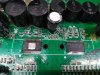
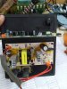
These four caps are the ones marked "330 25V RVT" as seen on the photo below:

1ZTuRYU.jpg


These caps have surface mounted terminal so it is not easy to rock it from side to side while heating it up to remove it. Care must be exercised to avoid peeling off the circuit board trace. Apply only gentle force while heating with soldering iron. To access the terminals of the capacitors you need needle tipped bit on your soldering iron. The space between the capacitor barrel and the board is very less. My regular 25W Soldron tip could not reach the cap terminals. I used a Goot with needle ceramic bit. Replacement capacitor diameter must be 10 mm or less to fit the available space on the board.


Second change one can make is to reduce gain. My boards come with 32 dB of gain. Here's the table from the datasheet showing the values of resistors:


Z3H3Jba.png


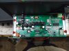
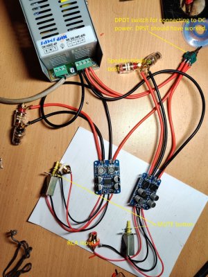
We need to change the values of R1 and R2 given in the circuit diagram. For 32 dB gain in Master Mode, the values of R1 and R2 are 39K and 100K Ohms. Note that the datasheet circuit example uses another set of names for R1 and R2, so it is best to identify them from the nearest pins on the amp chip. On the circuit board (at least mine), R1 and R2 corresponds to R28 and R27. See the first photo in this post for reference. If you remove R27 completely, the table shows that the gain will be 20 dB. This is the easiest path. However, 20 dB gain may be too less for some chains. I preferred 26 dB gain so I removed R28 = 39K and used 20K instead. Later I changed it to 27K for slightly higher gain. Since I don't know where to source SMD resistors, I simply used a regular 1/8W through hole, metal film resistors and soldered them carefully across R28.

Here's a pic of the 10K + 10K resistors in series on the top left corner near the orange capacitor. I didn't have 20K resistor so I had to use two. Later I had changed it to a single 27K:

IX6quqO.jpg


The blue "drop" capacitor riding piggyback on the orange capacitor is for bootstrap snubber, explained below.


Third mod I did was to fit bootstrap snubbers. These are basically one 330 pF capacitor and a 10 Ohm resistor in series, the 10R being grounded. Check out the diagrams below, borrowed from here:


boGTRQV.png


and the closeup below:


v9cSRJg.png


C10, 12, 14, 16 are the bootstrap caps.

C11 and R11 constitutes the snubber for the C10. There is no C11-R11 on the stock board, and that's what we need to install. C11 and C17 are the blue caps visible in the pic above.

Repeat for C12, 14 if you have a stereo board, otherwise ignore them if you have PBTL boards.

So basically for PBTL board you install:

C11-R11 for C10, and C17-R16 for C16.

Here's a diagram on how to implement it practically:

LCMEVcD.png


The 10R resistor is grounded on the negative terminal of the 330 uF cap, since the negative terminal of the 330 uF cap is at ground. One end goes to one lead of the 10 uH inductor. These are two convenient points to solder.

Also note that there is a small red line connecting R27 and R28. I use this since the pad of R28 fell off while desoldering.

The last mod is to put a capacitor of sufficiently high value across the DC input terminals - negative terminal of capacitor to negative of DC supply, positive terminal of capacitor to positive of DC supply. I tried 6800 uF/50V. You can safely use anything rated above 35V. This capacitor is supposed to provide some extra energy storage that can help stiffen the power supply line and prevent the power supply from sagging during high dynamic passages. Or at least that's the theory. I have removed this caps since it led to whining noise in one channel. The other is surprisingly dead quiet.

If you plan on the above surgeries, do be careful as the board traces are very thin and break easily.

Hi

I have experimented with snubbers, and in my case the above snubbers does not improve sound. I can hear difference in treble compared to my parallel LM3886 amp, the TPA3118 is more "harsch"/not completely clear. But after doing a lot of investigation on switched amps, I have found that there are two main problems causing distortion on switch amps, supply stability and dead time. Supply stability can be improved as described here by changing the capacitors to something better having lower ESR ratings. But the described snubber design shown does not help on dead time, it only dampens high frequency ringing, if present. On my scope I do not see any severe ringing, at least not in idle mode.
To compensate for the floating output during dead time, I have connected only one snubber between the output filer coils primary side (amplifer outputs). The function of the snubber is to prevent a floating output during dead time, and ideally it should have a large capacitance and very low or no resistance. But this is course not possible, since it would cause the amp go into protection mode due to too high switching current or too high temperature due to power dissipation. But I have now tester R=2,2ohm C=1nF, and it works fine. It really clears up the treble, especially on low to medium volume. The resistor is chosen to limit the switching current, so that it is kept below 15A. The capacitor can be larger, but higher value will cause more power dissipation. 6,8nF would give 2,1W loss in snubber resistor when there is output and 0,2W addition loss in the circuit. Since I only had 1W resistor available the capacitor of 1nF was used.
 
Hi...i have a doubt that san o/p capacitor on this circuit can burst if the circuit is powered on without connecting the speakers. What value of resistance can be permanently connected on the terminals so that the speakers are never open-circuited?
 

Attachments

  • maxresdefault.jpg
    maxresdefault.jpg
    113 KB · Views: 44
  • reconnect-electra-wireless-party-speaker-500x500.png
    reconnect-electra-wireless-party-speaker-500x500.png
    119.3 KB · Views: 52
  • WhatsApp Image 2020-02-11 at 6.58.32 PM (1).jpeg
    WhatsApp Image 2020-02-11 at 6.58.32 PM (1).jpeg
    123.8 KB · Views: 56
  • WhatsApp Image 2020-02-11 at 6.58.32 PM (2).jpeg
    WhatsApp Image 2020-02-11 at 6.58.32 PM (2).jpeg
    113.9 KB · Views: 57
  • WhatsApp Image 2020-02-11 at 6.58.32 PM.jpeg
    WhatsApp Image 2020-02-11 at 6.58.32 PM.jpeg
    109.8 KB · Views: 52
I did a number of things too that the topicstarter did, except for the bootstrap snubber. From one of my amps I hear some soft goofy sounds (like a dishwasher?) during silence. In the other too, but is it less pronounced.
What will the bootstrap snubber do? Will it remove this kind of "interference" sounds?
 
Hi

I have experimented with snubbers, and in my case the above snubbers does not improve sound. I can hear difference in treble compared to my parallel LM3886 amp, the TPA3118 is more "harsch"/not completely clear. But after doing a lot of investigation on switched amps, I have found that there are two main problems causing distortion on switch amps, supply stability and dead time. Supply stability can be improved as described here by changing the capacitors to something better having lower ESR ratings. But the described snubber design shown does not help on dead time, it only dampens high frequency ringing, if present. On my scope I do not see any severe ringing, at least not in idle mode.
To compensate for the floating output during dead time, I have connected only one snubber between the output filer coils primary side (amplifer outputs). The function of the snubber is to prevent a floating output during dead time, and ideally it should have a large capacitance and very low or no resistance. But this is course not possible, since it would cause the amp go into protection mode due to too high switching current or too high temperature due to power dissipation. But I have now tester R=2,2ohm C=1nF, and it works fine. It really clears up the treble, especially on low to medium volume. The resistor is chosen to limit the switching current, so that it is kept below 15A. The capacitor can be larger, but higher value will cause more power dissipation. 6,8nF would give 2,1W loss in snubber resistor when there is output and 0,2W addition loss in the circuit. Since I only had 1W resistor available the capacitor of 1nF was used.
Hi KJK,

I am curious what you mean by: " I have connected only one snubber between the output filer coils primary side (amplifer outputs)" . How does this relate to the TPA3118 board and the subber mod this topic is about? I have put in the original snubbers like the TS has described, which means one on either side. Do you mean you only do it one one side?

Also: you describe that the 10Ohm 330 pF solution does not work for you. Later on you state that 2,2 Ohm and 1nF cleans up the sound. Does this mean that you use those values instead of the original values and do you put in in the same location?
 
Intrigued by the high interest that the compact amplifier boards based on the family of Texas Instruments' TPA 3118/3116/3110 of Class D amplifier chips have been generating among the enthusiasts community worldwide, I decided to find out for myself what these boards sound like stock, and if the many modifications others have tried really do improve performance to a higher level.

This is the board I got, though mine was from eBay India. Each is a mono board so one needs two for stereo.

Below is an actual photo of one of my boards. They're very compact and measure roughly the same size as a credit card.

1ZTuRYU.jpg


There are many vendors selling similar boards on Amazon, eBay, Alibaba, Taobao, etc and there are quite a few variants to choose from. Just to give an idea of the variety, you will find stereo boards, stereo boards with volume pot, stereo boards with Bluetooth, and plain PBTL mono boards with double the power output of the stereo boards. The TPA3116 boards usually have some form of heat sink placed on top of the chip itself. Due to its higher heat dissipation ability, it can make more power compared to TPA3118 based boards. TPA3118 has heat transfer pad at the bottom of the chip and is supposed to transfer the heat to the circuit board itself, with the circuit board itself acting as the heat sink. Typical stereo TPA3118 boards produce about 30 Watts into 8 Ohm load with 24V supply.

The stereo boards typically come with a gain of 36 dB, making it quite suitable for plugging in portable players or smart phones directly. My boards came with a slightly lower gain of 32 dB. My understanding is this gain of 32 dB is still higher than the more typical 26-28 dB gain on most power amplifiers. The downside of higher gain is the higher noise floor.

If one wants to understand more about this chip amp, it is essential to go through the datasheet here. It gives all information needed by board designers, including example schematics on which most of the commercially available boards are based on. There is also information on how to change the gain of the amplifier.

The stock board is actually a very nice sounding amplifier. I drove it with my Kuartlotron buffer, the buffer acting as the volume control. The output of the TPA3118 board drives my 8 Ohm speakers. One can almost live with the sound of the stock board, except for a hardness in the midrange. This leads to a harshness and makes it difficult to listen for extended time. Though the datasheet example circuit specifies a load of 4 to 8 Ohms, it is my understanding from reading many hundred pages of forum posts that the output filter inductor of 10 uH is actually more suited to 4 Ohm load, and can be stretched to 6 Ohms. So if you want to drive an 8 Ohm load like me, the most fundamental change one must make is to swap out the inductors to the more correct value. I have variously come across 15 uH, 22 uH and 33 uH as being the best value for 8 Ohm speakers. I have not undertaken this mod as I am not sure about the value, and also because the cost of replacement inductors is going to be more than the cost of the board itself.

There are cheaper mods that will bring substantial improvements. The first and foremost is to change the four 330 uF/25V power decoupling capacitors to something better. I used 470 uF/35V Keltron caps. The replacement caps must be 10 mm diameter or less to fit within the available space, and rated for at least 25V. Changing to better capacitors completely removed the harshness that I heard. The stock caps are surface mount type. Care must be exercised when desoldering so as not to lift the pads. Caps with regular leads can be used as replacement by bending the leads carefully to match the pads on the board. This mod is the most important mod, in my opinion.

Next on the agenda was to decrease the gain from 32 dB to about 26 dB, mainly because I can hear a whining noise from one channel, and also because I was not happy with such a high gain. There are two resistors whose values can be changed as per the gain table given in the datasheet for setting the gain to 36, 32, 26 and 20 dB. The easiest to set is 20 dB because it involves removing one of these resistors from the circuit board. I wanted to set mine to 26 dB as that is closest to what I understood to be the gain of a conventional power amplifier (of course there are low gain power amplifiers like Firstwatt F5). This involved removing one of the two resistors mentioned above and replacing it with appropriate value. I am avoiding going into details like which R, which value, etc as it gets fairly technical, but if someone is interested, I can provide more info on how to go about it. But be warned that desoldering SMD resistors is not easy. Soldering back the replacement resistor is tougher, especially for someone like me with no prior experience of working with SMD parts. It's perfectly possible to brick your board. I very nearly rendered one board useless while desoldering the resistor as the PCB trace got lifted and fell off. Choosing your gain depends on how much gain you have at the source-preamplifier stages. If you have a 10-12 dB preamp stage, even 20 dB at the power amplifier stage (which this TPA3118 board is) ought to be sufficient. I would not use the highest gain setting of 36 dB as the noise also gets amplified by that amount. The next lower gain of 32 dB is also high.

The third mod one can do (with some caveat) is to beef up the power supply rail. I use 19.5V/4.7A laptop (one per board). I used a 6800 uF/50V capacitor across the 19.5V DC supply into the board (+ve terminal of capacitor on +ve terminal of the supply, -ve terminal of capacitor on -ve terminal of the supply). I use two laptop bricks from two different brands, though they have exactly the same voltage and current ratings. One channel powered by brand X adapter had been consistently having a high frequency whine audible even when the volume control is zero. The volume of the whining noise does not increase even when volume knob is turned up. I tried a simple R as well RC filters across the source RCA socket but neither had any effect on the whining noise. A couple of days back I noticed that one channel is sounding lower than the other side. I rechecked the values of the resistors I used on both channels and discovered that they were not closely matched. Later, I used closely matched resistors but still had channel imbalance. I reflowed at solder points on the board with the lower gain, in the hope that it could cure a poor solder but that didn't help either. Finally, I took off the power rail capacitor (6800 uF that I had fitted) on both boards, and that instantly cured both the channel imbalance and the whining noise. So in effect I had introduced two problems when trying to beef up the power supply rail. This is very likely because of a degraded capacitor as the other channel worked perfectly. Hence the caveat at the beginning of this para. I may re-use proper CRC at the supply rail when I can buy fresh capacitors. For now I am running without them.

The last mod that I did was to use bootstrap snubbers for the output inductor filters to reduce EMI that can arise by the switching of the output stage (sudden transients into inductive loads produce EMI). The "output" side of the inductors already have snubbers by way of the zobel network. What is added is a C and R before the signal reaches the inductor. This additional snubber cleans up the sound further.

There are further mods like playing around with different switching frequencies, but I don't plan to play around with these boards any more. I am afraid I will brick them as the thickness of the copper pads is thin and cannot withstand multiple soldering/desoldering.

In a coming post, I will post about my impression of the sound after all these mods.
Hi, I have one tpa3118 with bluetooth, (sanwu) the sound at high volumen become so distorted, after removing the 100K resistor the sound become much better (no distortion) but to me is a little low. Can you tell me the value of the resistor you solder on the board instead of the 100K smd resistor. Kind Regards. Orson Parra.
 
Last edited by a moderator:
Check out our special offers on Stereo Package & Bundles for all budget types.
Back
Top