New Design, SE 6005 Directly Coupled Audio Amplifier

Status
Not open for further replies.
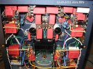
12- 11 -2021 Mini Photo Update ............ Ground BUSS, ........... Each Channel - to STAR Central Ground


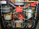
12 AWG Mil Spec wire, Teflon jacket stripped- off below photo. Beautiful quality silver plated copper stranded wire, leading to STAR GROUND, the central chassis brass bolt.

013.JPG


ON RCA Input Jacks : " Delicious sounding " 430K Shinkoh TAF half Watt tantalum resistors, best sounding resistor brand of six different resistor types we tried. ( start out - on the right foot !! ). Shinkoh tantalums are no longer manufactured.


007 edited 4.jpg

Notice how bare 12 AWG Mil Spec ground buss wire crosses the chassis filament wires, not touching AND at 90 degrees for minimal interference.

Thank you - for looking.

Jeff
 
Last edited:
12- 11 to 13 - 2021 .............. Mini UPDATE ....................Photos

We decided on 12-11-21 that the new " Double Final Filter B+ MODULES " will be much better positioned if reversed, or flipped 180 degrees, against the chassis side walls. Much more spacious and easy to work on, to wire, etc. We greatly prefer the new flipped orientation on the right side, below.


008  EDITED XLNT FIRST.jpg

013 EDITED EXCELLENT.jpg


To execute " flipped Modules " we will have to re-do some of the previous work. Started by re-doing the two small round black RLB9012 Hash Chokes, for the input tube's filament lighting. We also " flipped them " 180 degrees, and placed them out of the way, as much as possible. Right against the Keystone 817 terminal strips.

001 EDITED OK.jpgEDIT 2.jpg

This slight hash choke repositioning will allow for more room to better optimize the triode's plate ( Ra ) and cathode ( Rk ) resistor installation, to be added next at the tube socket. ......... Coming up soon.


Jeff
 
Last edited:
12-13-2021 Mini Update ........ The Cathode Resistor ( Rk ) ........ and it's highest frequency bypassing

We think it is counter- productive not to use the best possible resistors, differing by brand and type, in each and every different resistor location inside the amplifier. Resistors effect the sound of the amp as it plays back music.

The Input tube, being higher in overall gain than the Output tube, is particularly an important spot to optimize. " If you lose the least bit of music signal in the Input stage, the music's information will never get " made up " in the later stages, eg, the Output stage.

As of 12-2021, one of our favorite resistors for the input tube's cathode ( it's return-to-ground resistor, or Cathode Resistor or " Rk ",........ k for Cathode ) is a Caddock TF020. Our favorite source for a TF020 is from Michael Percy in the USA. Read the TF020's description in Michael's Catalog. Doesn't it sound delicious , "yummy " truly capable ??


Capture.JPG

As you know from this thread, we strongly believe in the artistic use of multiple film cap bypassing. ( No single cap is good enough, in all the frequencies ! ) Whereas most all else in audio will use only one cap in a cap position, we routinely use five FILM caps, or more !!

To retain the music's highs, previously mentioned in this thread, we may use a 0.033uF and 0.01uF values, in combination. The smaller the value of the cap, the more URGENT is is that the cap be placed close, lead-length-wise, to it's place in the circuit. Too long a lead length, and the smallest caps play- back effects are NEGATED. You will not retain the music's highs .... at all. You might as well not add such a cap, if the lead length is long.

We are very happy today.

The ultra critical Input tube's Rk ( a Caddock TF020 ) has been configured with our two " higher frequency " bypass cap values, and we have managed to get the caps ( only one cap value shown, 0.033uF ) placed literally, " right on " the resistor, with a minimal lead length.

The 0.01 uF WIMA 630 VDC cap will also be similarly placed, lead length wise, onto the Caddock TF020 cathode resistor. We are so pleased to have this executed these parts in such a manner. We will now expect ( and hope for ) truly lovely highs from this design and implementation.


033edit 2.jpg


048 edit 1.jpg


047 edited.jpg

It is really a lot of fun, to hear a tube amp, that does not as usual mainly only " play the midrange ". Lets construct something that plays back music with an extended and thrilling-to-hear top end. It has to be built that way, to obtain it !!!

Thanks for looking.

'' Hope we are not boring people with all these DIY posts. Too much ??? ???

Jeff

PS:

Very recently we had moved the two filament hash chokes, closer to the chassis floor, and away from the Input tube's 9 Pin socket. This has now given us room, to add this new Rk assembly, with ease !!! Hooray.
 
Last edited:
12-14-2021 Mini Update

018 edited NUMBER 3.jpg


017.JPG


Short as possible lead lengths for these two higher frequency film bypass caps. Three additional caps, to cover well the entire audio spectrum for this Rk resistor, ( much larger uF value film caps, for the mids and lows ) , are located on a separated " Rk Bypass Module" close by.

- - - - - - - - - - - - - - - - - - - - - - - - - - - - - - - - - - - - - - - - - - - - - - - -

Here below is how a Jadis ( France ) " Signature " DA50S integrated amp uses a single High power Rk ( green , wirewound ) to bias a Push Pull pair of output tubes. ( Very good engineering ! ) We just got this Jadis amplifier delivered to our door - only yesterday.

This very nice integrated tube amp sold for about $10.000 six years ago, current model, now with a remote, is about $13,000 . As you can see in our photo, for the Rk bypass, it uses a single electrolytic bypass cap.


012 EDITED 1.jpg


An Rk's bypass cap is IN the audio circuit.

Question : Would you use an electrolytic...... as a coupling cap ????

Is there a better way ?


Jeff
 
Last edited:
12-15-21 ....................... Mini Update

Actually building AUDIO section.

For both channels, installed Caddock TF020 Rks ( cathode resistors ) , and their two high frequency bypass caps onto the input tube sockets. Jumpered ( 2Xs Wonder Wire ) from each tube socket's " Cathode" PIN to a nearby " Rk Module", containing three larger film caps - for lower frequency all-film cap bypassing.

Installed the Direct Couple ( D.C. ) connection, from each 6N23P-EV input tube's plate to each 6005 output tube's control grid, using doubled - up Wonder Wire again, lightly twisted. The doubled Wonder Wire is superb sonically, superior in the locations shown - to our often favored Mill Spec m22759-11.

Next to do : install the " DF FFs " or Dennis Fraker Final B+ Filters, and the Plate Resistors ( Ra ) for each 6N23P-EV input tube.

Music in two more days ??? Maybe. Two to four days. The chokes we greatly prefer to use, two six Ohm Hammond 159ZAs, take a full 75 hours to break in and to sound right.


011 edited.jpg


Count them, five film caps to start with, for each cathode resistor bypass. Everyone else might use one cap, often an electrolytic.

Jeff
 
Last edited:
12- 16 -21 .......................... MINI PHOTO UPDATE,........... Very SHORT ....................


001 EDITED WELL.jpg


Just a few more days ?????

G2's ( Double B+ Filters ) for the Output tubes ( 6005 ), and the Output tubes' Rk MODULES, and Rk Heat Sink, need to go in, as does Input tube's plate resistors. Steady at it.


Thanks for looking. Best wishes.

Jeff
 
Last edited:
12-17-21 ............................................... Mini PHOTO update

Estimated........ two more days, until fire - up .


001 EDIT 3.jpg


006  edit 3.jpg


009.JPG


011 edited date.jpg

................................................................................... Above, single star GROUND, ...... 14 and 12 AWG m22759/11 ............................


This build thread ( D.I.Y. ) started 49 weeks ago. Thank you for looking, following along. We need to show you some good photos of the TOP SIDE of the amplifier soon. It is interesting to look at, ..... three customized R-Core transformers above !!

A second unit is in place, waiting our finalization. Six units total.


Jeff
 
Last edited:
Staggering amount of work to do all that for multiple amps, thank you for the update.
 
A very crowded under-chassis... but, of course, you don't have to throw a pin inside! Are you sure that you need this over-engineered layout? But... afterall, sonic impression counts, in the end. Hardly waiting for your opinion after the first fire-up... In my opinion, it is very hard to make things right, with a steel chassis. I use wood chassis and solved a lot of problems.
 
Staggering amount of work to do all that for multiple amps, thank you for the update.


Hello !!

Welcome to Hi Fi Visions.

A very good group of people here - these India based people. !!

Enjoyed reading your first introductory post. Continue please to contribute !!

Half of these six new chassis ( and Shilchar R-Core Power transformers ) are earmarked for three very good DIY audio friends.

All three people requested guidance on TYPE 45 Direct Coupled amp design. In clear conscience we had to talk them out of it and come up with something we know to be much better performing - when playing ALTEC theatre speakers full range. The many pictures posted were partially for these people, to reference back to as they build amps for their own in-home use.

It is "positive" to share ideas with friends who have a common interest !!

Jeff
 
A very crowded under-chassis... but, of course, you don't have to throw a pin inside! Are you sure that you need this over-engineered layout? But... afterall, sonic impression counts, in the end. Hardly waiting for your opinion after the first fire-up... In my opinion, it is very hard to make things right, with a steel chassis. I use wood chassis and solved a lot of problems.


Welcome to Hi Fi Visions.

Yes, we are very sure " the over engineering " is necessary.

Why ???? Because we have been LISTENING to the result of such, over four decades of building amps. What we do is all - very audible !!

People try to " get by on using nothing ", and it is usually not the very best possible result.

- - - - - - - - - - - - - - - - - - - - - - - - - - - - - - - - - - - - - - - - - - - - - - - - - - - - - - - -


We never use a wood chassis, except sometimes as a thin " visual " exterior trim, applied to a 12 or a 14 gauge ( heavy, rigid ) steel chassis underneath.

In our opinion, a wood chassis can catch on fire, and burn your house down. Wood offers no shielding.

Wood chassis is primarily seen in the realm of amateur DIYers , typically operating with insufficient funding and experience. ( Yes, there are exceptions to this ).

Do we see wood chassis on brands such as Audio Research Corp, or McIntosh Labs ( USA ) , MBL ( Germany ) , Jadis ( France ) ? .......

No, of course not. ........ Not at all. ............. Why ???

One other thing, you have to engineer to best use a steel chassis in audio, very few do this, very few.

- - - - - - - - - - - - - - - - - - - - - - - - - - - - - - - - - - - -


Again, a sincere welcome to HFV and best wishes to you in this audio hobby ,

Jeff
 
Last edited:
12-18-21 ......................................... Mini ................................ 3 Photo UPDATE


005 Date EDITED.jpg


........................................................................................................Look above Ma, NO coupling caps......................................................................................


007 edited.jpg


008 EDITED.jpg


......................................................................Grid 1 above is the DC couple. Hoorah !!!!...........................


Thanks, for looking. Best wishes.

Jeff
 
Last edited:
12-19-2021 ......................... Big REPORT...............................Perhaps ONE day AWAY from being DONE ???? !!!


In these first 3 photos : we added Doubled-Up Wonder Wire, solid core 19 AWG,

* from 6005 output tube's tube socket Cathode PIN,


* to Heat Sinked Rk ( Rk = Cathode Resistor ) and

* from Rk to the newly developed all film bypass Rk MODULE.


011.JPG012.JPG013.JPG


Picture 4, below :

Added Plate resistors to Input tube's anode ( the Direct Couple ) . Plate resistors are highly audible - these shown are doubled-up 2 watt MK8 Rodersteins, a great sounding Ra , matched to 0.01% - for no skewing.

Added the High Frequency film cap bypassing cap pairs ( in white circles ) to each 6005s' Rk. We had to space the film cap pairs a bit away from the Rk and Heat Sink, to avoid long- term HEAT damage !! ( 14.5 Watts continuous dissipation, from both the channels' Rks, in total ).


018 (2) EDIT.jpg

As we look at the above and below photo, the 12 AWG YELLOW B+ wire, on either side of the amp needs to be re-done !!!

No need to tuck it under the lip, in a large " U" form. . We can reduce the wire run by maybe 40%, simply by wiring the two connected points DIRECT to each other. Use the internal chassis space in all three dimensions.
It is usually good practice ....... to reduce lead lengths when possible.


019 (2) FULLY EDITED.jpg


021.JPG


We have developed a unique solution for the filament wiring, and managing their fields, so as not to needlessly degrade the B+ wiring.

The top-side of this chassis will be truly FUN to show you all. Within a couple of days !!

Thank you for your continued interest.

Jeff
 
Last edited:
12-19-2021 ......................... Big REPORT...............................Perhaps ONE day AWAY from being DONE ???? !!!


In these first 3 photos : we added Doubled-Up Wonder Wire, solid core 19 AWG,

* from 6005 output tube's tube socket Cathode PIN,


* to Heat Sinked Rk ( Rk = Cathode Resistor ) and

* from Rk to the newly developed all film bypass Rk MODULE.


View attachment 65416View attachment 65417View attachment 65418


Picture 4, below :

Added Plate resistors to Input tube's anode ( the Direct Couple ) . Plate resistors are highly audible - these shown are doubled-up 2 watt MK8 Rodersteins, a great sounding Ra , matched to 0.01% - for no skewing.

Added the High Frequency film cap bypassing cap pairs ( in white circles ) to each 6005s' Rk. We had to space the film cap pairs a bit away from the Rk and Heat Sink, to avoid long- term HEAT damage !! ( 14.5 Watts continuous dissipation, from both the channels' Rks, in total ).


View attachment 65419

As we look at the above and below photo, the 12 AWG YELLOW B+ wire, on either side of the amp needs to be re-done !!!

No need to tuck it under the lip, in a large " U" form. . We can reduce the wire run by maybe 40%, simply by wiring the two connected points DIRECT to each other. Use the internal chassis space in all three dimensions.
It is usually good practice ....... to reduce lead lengths when possible.


View attachment 65422


View attachment 65421


We have developed a unique solution for the filament wiring, and managing their fields, so as not to needlessly degrade the B+ wiring.

The top-side of this chassis will be truly FUN to show you all. Within a couple of days !!

Thank you for your continued interest.

Jeff
BEAUTIFUL BUILD, Jeff.

CONGRATS
 
12-20-21 .................................................. Mini Photo REPORT....................................GOOD and BAD !!!!!!!!!!!!!!!!


As of this morning, we have the first stereo amp 99% done, and ready for first complete ( power supply PLUS audio stages ) fire up, using a " borrowed " line cord and 20 Ampere rated IEC connectors. Herein follows three below-the-deck photos.

We are finally very pleased with this MODULAR ( eight modules total ) approach to to this build in 2021. Almost every "capacitor position " inside the amp has multiple film cap bypassing. The parts , layout, and future serviceability is GREATLY enhanced with four " Rk MODULES " and four complex ( C - L1/C1/L2/C2 ) Dennis Fraker " Double B+ FINAL FILTER MODULES ".

Additionally, this amplifier is unique - by using six ( total ) current SHUNTS, B+ to ground, which stabilizes the B+ to G2 ( for the Output tube, a 6005 tetrode ) and for the Ra ( the plate resistor of the Input triode tube . )


004.JPG

Notice above ( and the photo below ) our NEW way to run the filament wiring ( grey and white twisted ) away from the other wiring, for less field interference between wiring. This is our newest idea implemented.


006.JPG


007.JPG


Now for the bad news.

We went to fire this up, this afternoon, and we cannot insert the Input tubes ( 6DJ8 triode types, Russian 6N23P-EV ) into the amp's 9 PIN tube sockets. Neither Input tube would fit either socket. !!! A mystery.

Under good lighting, we see that both of the vintage NOS Amphenol 9 PIN sockets have their " PIN #5 " location FILLED with solder. Both tube sockets, the same . Were these defective sockets, unknowingly
sold to us on eBay ??? Look :


015  EDITED USE !!.jpg


The only way to fix this is to disassemble the amp's Input Stages, and replace the tube socket. A lot of extra work.

This photographed amp belongs to me, it gets done first, as the guinea pig.

A second amp for a Client, will get these same Amphenol sockets installed, either today or tomorrow. IF their PIN #5 s go bad, ALL these 9 PIN sockets are defective !! AMPHENOLS were specifically selected because their contacts are phosphor bronze, and thus superior to most other vintage sockets.

We may not be able to post ..........being busy with disassembly, repairs, and trouble shooting !!

Thank goodness, these amps have removable MODULES !!!

After almost a year, we were curious to see how all the voltages measured VS. our calculations on paper !! So close, but far away. Solvable.

Thanks for listening, viewing.


Jeff


PS: We really like this Midnight Blue WRINKLE powder coat finish, for it's color, finish and durability-wise. Eastwood makes it.
 

Attachments

  • 007.JPG
    007.JPG
    692.9 KB · Views: 19
  • 006.JPG
    006.JPG
    394 KB · Views: 20
  • 004.JPG
    004.JPG
    652.8 KB · Views: 21
Last edited:
Addendum to 12-20 Progress REPORT :

It is
PIN #6, the plate , not PIN #5. This solder blob / solder migration was very likely totally my error, when attaching the doubled up 19 AWG Wonder Wire !!! There was likely nothing wrong with the NOS AMPHENOL tube sockets.

Maybe I can reheat it, in place, and see what a solder sucker can do. But then there will be solder residue on the PIN contacts. After going to all this effort, to optimize the circuit and this audio amplifier's design, it seems highly counter productive NOT to replace the socket completely, and solder more carefully the doubled up Wonder Wire !!

TO minimize such errors in the future, arriving today, we received TWO new lights, for assembling amplifiers, etc etc etc.

Ott-Lite 13BRB is the name and a model number. Available used from eBay, circa 2004 date code. It provides a natural light spectrum. with a 13 Watt fluorescent bulb. Two units are ideal, for doing an amp, or sewing, jewelry making, etc.

An audio manufacturer I know has used one for years. Not expensive if purchased used. Last week we got four nice ones for only $40.00 USD plus shipping. https://www.ebay.com/itm/154399968915. These were costly, new. Highly recommended product !!! Operates on 120 VAC, use a step down transformer if on 230 VAC.

Jeff
 
Last edited:
Maybe I can reheat it, in place, and see what a solder sucker can do. But then there will be solder residue on the PIN contacts. After going to all this effort, to optimize the circuit and this audio amplifier's design, it seems highly counter productive NOT to replace the socket completely, and solder more carefully the doubled up Wonder Wire !!

It must be possible to push the pin#6 a bit and pull it out from the other end using a nose plier. Once the pin is out of the socket, it will be easier to remove the solder.
 
A very crowded under-chassis... but, of course, you don't have to throw a pin inside! Are you sure that you need this over-engineered layout? But... afterall, sonic impression counts, in the end. Hardly waiting for your opinion after the first fire-up... In my opinion, it is very hard to make things right, with a steel chassis. I use wood chassis and solved a lot of problems.
There is nothing about this build that is the result of being "over-engineered". In fact, the multitude of space-consuming paralleled capacitors are nothing more than a multitudes of band aids that are used in an attempt to mitigate the gross interstage and intrastage coupling via the power supply lines that exists almost entirely because of the 19th century style unregulated power supply that is used. Worse yet, because of the use of a totally unregulated power supply, the performance of thiis amplifier is going to be highly dependent on the impedance characteristics of the loudspeaker load to which it is connected.
 
Thank you for reading and for your input, Dr. Gary. I understand that my enthusiasm can sometimes be interpreted in other ways.

What I can say is that, even if I am not an E.E., nor have a PhD like you, my joy in building and listening and freely-exchanging ideas for the love of the hobby is the point. I have come to this point honestly over about 40 years.

This admittedly unconventional approach works well for me and others I trust, and it is offered freely.

YMMV.

Jeff
 
Last edited:
There is nothing about this build that is the result of being "over-engineered". In fact, the multitude of space-consuming paralleled capacitors are nothing more than a multitudes of band aids that are used in an attempt to mitigate the gross interstage and intrastage coupling via the power supply lines that exists almost entirely because of the 19th century style unregulated power supply that is used. Worse yet, because of the use of a totally unregulated power supply, the performance of thiis amplifier is going to be highly dependent on the impedance characteristics of the loudspeaker load to which it is connected.
Looks like you have heard this amplifier for long duration to arrive at this conclusion or are you speculating and have lots of free time?
 
Status
Not open for further replies.
Order your Rega Turntables & Amplifiers from HiFiMART.com - India's reputed online dealer.
Back
Top