New Design, SE 6005 Directly Coupled Audio Amplifier

Status
Not open for further replies.
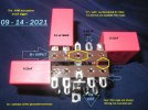
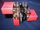
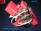
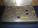
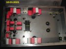
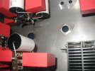
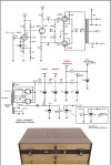
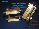
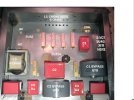
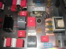
I have a lot of film caps and associated parts to add to this stereo amplifier build, so I must build "UP" in three dimensions, and not just lay out the amp in two dimensions, as most builders do.

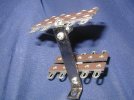
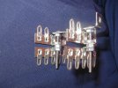
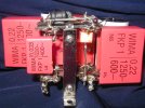
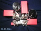
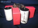
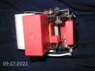
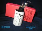
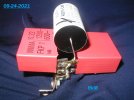
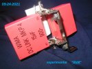
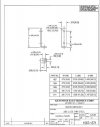
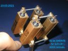
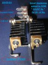
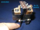
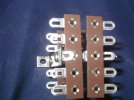
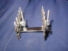
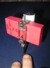
Today I designed a simple "build module", which will allow for many parts to be positioned, in the vertical axis. It only takes one bolt to attach the module to the all-steel 14 gauge chassis. Uses Keystone 817s and a Keystone 1567.

012.JPG004.JPG011.JPG009.JPG

Very simple construction.

Jeff
 
09-13-2021 MINI UPDATE

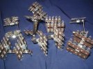
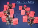
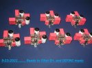
Today was spent carefully building eight of the newly- designed " VAM"s or "Vertical Attachment Modules". A dozen parts, including 9 high quality film caps, are to be attached onto each module .

These eight VAMs will be used in two stereo amps.

005 (2).JPG


A single VAM feeds cleaned-up B+, to each channel's Input tube...powering the plate's resistor ( Ra, or R anode ).

A second set of VAMs will feed greatly cleaned-up B+ to each channel's output tube " G2" grid .

A " G2" grid exists in a 6005, which is a tetrode output tube. The G2 supply, ideally, has to be the most carefully executed in the amplifier. Sadly, it almost never is. ( However, this particular 6005's G2 B+ is quadruple series passively filtered. Each channels' G2 "VAM" provides two of four passive B+ filtering stages . I have never seen this done before in audio. I briefly heard this quadruple filter in the prototype, in about 3-2021, and loved it !! ).

It is commonly said, and commonly known, " the best way to run a tetrode ( or a pentode) is with a really superb G2 supply." But in practice, everyone I see " cheaps-out " and no one does G2's B+ really well.

All the modules' nuts were securely tightened. I used Loctite brand " Threadlocker " in lieu of lockwashers. This is a removable treatment, a blue liquid, # 242 .

The next task over the coming few days is to figure out how to best position, wire, and solder each part ( nine film caps, two small one Ohm filter chokes, and in some cases - a high-quality plate resistor ) to a VAM.

Once these VAMs are fully parts-populated, one needs to figure out how they should be best positioned, ( inside a space-restricted stereo amp.)


Monoblocks are much easier to build

I hope you approve of the term " VAM", as it was just made-up when posting here today. I thought it was a good honest description - ' liked it.

Amps ideally should be laid out in all three three dimensions, not just in two dimensions as we almost always usually see. Vertical is often not fully-considered . " To VAM, or not to VAM, that is the question ". .............................Shakespeare / Hamlet

Jeff
 
Last edited by a moderator:
09 - 14 - 2021 MINI UPDATE

008 edited.jpg
009 edited.jpg011.jpg


Next, finish building this first first ( ever ) VAM, and neatly duplicate seven more .,........for two stereo amps. Many others solder better than I. That is OK with me. " The bigger the glob, the better the job ". ;)

Thank you - for looking. I hope some of you enjoy this build.

Jeff
 
Last edited:
09-17-2021 MINI UPDATE

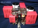
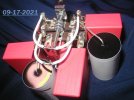
Finished today the first of the 6005 amp's four needed Vertical Attachment Modules, or "VAM"s.. This is a unusual double series passively filtered B+ assembly.

It is designed to " clean up " the B+ at the actual point of use. It is a low DCR ( about 2 Ohms total ! ) " Final Filter ". A single module will " clean up " the B+ to the Input tube, separately, at the left and right channels. ( Always remember this : If we lose ANY music information at the Input tube stage, it NEVER will get " made up ", later-on in the amplifier ! ) .

A similar pair of modules will "clean up" the ultra sensitive tetrode " G2" connection to the Output tubes', for the left and right channels.

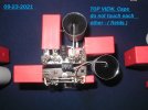
This " VAM " consists of a 15 uF / 900 VDC 4 pin WIMA main filter cap, followed by a small round black choke, followed by four different ( each smaller value) film caps. This completes the FIRST, of two identical passive filter sections.

A duplicate second filter section - "starting with a second black round choke, etc., cleans up" whatever the first misses - to be bullet-proof under music's dynamic conditions. The smaller the film cap value, the higher-up it plays in the music spectrum. ( Multiple film cap bypassing, this is called. ) Parts values and film cap choices are solely determined by ear.

A completed VAM module could be EE notated as : C ( =15 uF ) / L1 / C1a, C1b, C1c, C1d / L2 / C2a, C2b, C2c and C2d.

Almost all Manufacturers and DIYers will not do all this extensive "final filtering", primarily out of sheer thoughtlessness ( their self- ignorance ) and secondly, out of their own cost-containment issues and limitations.

036.JPG025.JPG037.JPG031.JPG032.JPG047.JPG

Three more VAMs to build for this stereo amp, and another four VAMs to build for a second stereo 6005 amplifier that goes to Hong Kong. These VAMs will get bolted to the side walls of the new stereo amp chassis, to better utilize internal chassis space.

I consider these VAMs mandatory in my SE DC amps - to achieve the best attainable resolution and dynamics. This double passive filter assembly puts quality film B+ storage caps within 1 /8 th of an inch from where they are being used .......... not four to eight inches away in the chassis .......as almost everyone else in tube audio design does !!!

Notice the build, how none of the nine capacitor bodies touch each other. They are positioned such that their fields do not interact negatively with each other. The Devil is in the Details.
 
Last edited:
09-23-2021 MINI PHOTO UPDATE

027.JPG028.JPG001.JPG019.JPG


LOL, on second look : .....( above ) ..........guess it really should have been Labeled " Ground Wires, White ".


021.JPG024.JPG


Ran out of solid silver-content hook up wire, so the eighth module awaits more 19 AWG " Wonder Wire " arrival.

' Been busy building - the last few days. 'Happy these are finished .

MUCH MORE ..... TO DO !! Parts are on hand.

Just the thought of what these B+ filters do musically, enables ( and actually encourages ) me to " hang in there" and patiently construct them.

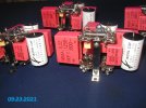
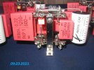
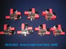
Eight VAMs ( Vertical Attachment Modules ) are used as part of the final filtering for two stereo 6005 SE DC amps presently under construction. These modules double- L/C- filter the B+ voltage to the Input tube's plate resistor, and another module double-filters the tetrode Output tube's internal grid ( G2 ).

Thank you - for looking.

Jeff
 
Last edited:
MINI UPDATE 09-24-2021

Early today, the final ( eighth ) VAM ( Vertical Attachment Module ) was completed.

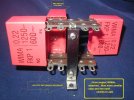
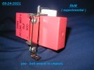
I have spent time today experimenting with a new needed module, the Cathode resistor ( Rk is the E.E. term ) bypass capacitor module, ( RkM is the new term, ( while we are naming MODULES - in this amp's design. )

A cathode ( "k" is the E.E. term ) resistor ( "Rk " ) in my amplifier has added to the Rk an all-film bundle of multiple caps, five usually.

A separate " RkM " is needed for each channel's Input tube ( 6N23P ) cathode resistor and for the Output tube ( 6005 ) cathode resistor.

Here pictured below, is what I have experimentally put together
. It covers the "main" bypass cap ( 15 uF WIMA / 900 VDC / 4 Pin , a lovely sounding cap by-the-way ), and the next two smaller caps of the paralleled bunch. ( three total - of the five used ).

There now is a need to "stare" at this assembly for a day or so, and determine if there is a better way to execute the design. If not, four RkMs get built, one each in the stereo amp's four signal tubes.

In another post, I will discuss the " ins and outs " of a vacuum tube's cathode resistor, and how it can be bypassed effectively. Allow me time to show this arrangement, posted below, to my Audio Mentor - and make a final design decision.

002 edited 9-24.jpg009  edited 9-24.jpg003 edited  9-24.jpg005  EDIT USE.jpg


The single-bolt chassis-mount allows for placement precisely where it is best in the chassis, and it allows for angling precisely. Good layout and chassis wiring is ultra critical for high performance, especially in a Single Ended amp.
 
Last edited:
09-25-2021 PROGRESS REPORT

An hour after posting, and trying to visually imagine the " experimental "RkM " bolted to the bottom of the audio chassis, lightning struck, and a solution was discovered - precisely what to do.

It is no longer " experimental ". I was so happy.

That bundle of three film caps ( 15uF, 0.68uF and 0.22uF ) was too large and it sat too low in the chassis.

The RkM's large size and lowness to the chassis, would cause it to interfere with other needed circuit wiring ( such as the filament wiring and the direct coupling wiring ), all occurring at " tube socket " pin height - estimated to be about one half inch off the chassis floor.

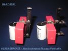
All that was needed was to transpose the same triple large cap assembly from the shortest Keystone Board Bracket ( #1567 ) to their tallest one ( #1569 ). Now, the entire film capacitor bundle can be positioned ABOVE existing components, and at more positions on the chassis floor, and at any angle required.

The vertical axis, nicely ............. to the rescue !


KEYSTONE 1567 ETC..JPG


A hole needs to be drilled 1.5 inches below the #1569's stock top-most bracket hole, to maintain the #1567's 1.5 inch bolt-on spacing. That is all . ( The "S" dimension in the datasheet .)

The remaining smallest two ( of five) bypass caps, ( their uF size-selected for augmentation of music's lower-highs and highest-highs ), gets soldered directly at the " point -of-use " right across the tube's cathode resistor, at the tube socket. Close to zero lead length, ..... which is electronically ideal.

Please note : conventional tube amplifier builds we see, most of the time, pay considerably less attention to the Rk and it's capacitor bypass, or, they usually find several more nasty-sounding ways to avoid the task. There is no free lunch.

We usually see a " quality " electrolytic. How can any " quality electrolytic " compete with a carefully-chosen bundle of film caps, selected by ear ???? Well, ....it can't.

Realize, the Rk bypass cap is IN THE AUDIO CIRCUIT, in a similar fashion as a series coupling cap !!

Would we use a " high quality electrolytic" as a coupling cap ? Of course not !! Never. We would instead use an expensive film cap, as good as we can afford if we sought highest performance.

However, 99.99 percent of amps one sees, uses an electrolytic Rk bypass caps, a " quality one" .... without much additional thought of how to execute the circuit better.

Parts quality in a simple two-stage directly-coupled amp, ( an amp that is being built for all-out audio performance ), is critically important. Nothing can be taken for granted, ALL is audible. Every resistor, and every run of wiring in the amp, must be selected not only to be electronically sound, and also be carefully selected by ear, for optimal sonic performance. Yes, every single inch of wire !! And the amplifier MUST also be laid out intelligently, if you want to " boggie on a world-class basis " when hearing your favorite music played back to you.

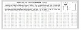
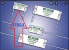
The Rk of my 6N23P Input / Driver tube does not dissipate a whole lot of power when in use. A small fraction of a Watt. This allows the use a really nice-sounding quality Rk, among the best ever manufactured. It is a Caddock TF020. Here is the write up....sounds delicious in writing, and it is awesome / lovely to hear. Would you pay $6.50 USD for a single 0.33 Watt resistor? I will .

Available from Michael Percy Audio in the USA, here is his Catalog description :

Caddock TF020  .33 Watts.JPG


......................................Caddock TF020 photo.JPG


By the way, I would highly recommend M. Percy as a source for better parts, and I believe he ships Internationally. Decades of quality service, and a great person to deal with. Add him as one your quality parts supplier !! A+++. Download his 2-2018 catalog.

Thank you for looking and following along. This is so much fun.

Jeff
 
Last edited:
Those Wima red bricks look like “candies” to me. Would not mind hoarding a few sacks of them if a deal happens !

BTW in audio signal path, how do the Wimas compare to the Russian PIO and Hybrid PIO ?

I need to do a comparison myself between a few caps, someday.

Yogibear,

A " deal " happens on WIMA caps, well selected ones, every single day of the year, at their retail prices !!!!

They are industrially priced, not " audiophile " priced.

They will often outperform the usual Russian surplus caps DIYers use IMHO.

When you say " audio signal path " I am not sure precisely what you mean. Are you referring to a coupling cap?? If so, I have little experience as I try to avoid coupling caps in designs whenever it is possible. Hence, direct coupling, ...... ( a few runs of Cardas 19 AWG solid silver wire, outperforms every coupling cap - and every interstage transformer, ever invented. That should be evident to people. )

In general, some Manufacturers use WIMAs as coupling caps, but I personally feel WIMAs are not good enough in that position in a circuit.

- - - - - - - - - - - - - - - - - - - -

IMHO, every cap in a SE amp is IN the signal path, because you certainly can hear every single one of them in any position - if you build transparent quality SE amps.

Notice, I only employ film-type caps, no electrolytics.

- - - - - - -- - - - - --- - - - - - -- - -- - - -

I use selected WIMA DC Link film caps, as power supply caps - in most cases. I prefer to augment ( bypass ) the WIMAs powering the output stage with ultra-high peak-current industrial pulse-duty caps, capable of 1,500 Amperes PEAK Instantaneous. This large round grey-colored 5 uF bypass capacitor is called a GTO cap. It does a wonderful job. It totally defines the leading edge of music transients, which is totally missing with all other caps I know of. So much FUN to hear, really fun !!

Specifically Yogibear, to filter the output stage I use a L1/C1/L2/C2 topology, and C1 and C2 get GTO bypassed. Leave C1 or C2 UNbypassed, ( missing either GTO ), and the amp dies, is boring, .... no fun at all to hear IME.

In Rk bypass duties Yogibear, WIMAs are NOT nearly as good as Mundorf Supreme Silver and Oils, but at a mere fraction of the cost, the WIMAs can be a useful choice.

In power supply positions, certain WIMA DC LINK sizes and uF values are superior sounding - than other WIMAs !

To save people the trouble : for a 50 uF supply cap, use a DC LINK MKP4, 800 VDC rated with four pins, NOT two pins. In smaller uF sizes, the 15uF WIMA DC LINK MKP4 with a 900 VDC rating, and four pins, is THE one to use and listen to !! It is wonderful-sounding, ..... highly recommended.

COST : Mouser shows the preferred 15 uF WIMA part at $5.00 to $6.00 USD. The 50 uF part is about $16.00 USD. Previous to the discovery of this 50 uF cap, from 1989 on in SE amps, my Audio Mentor used 47uF plus 47uF high voltage Blackgate "WKZ" Electron Transfer caps, which are no longer made.

In 2021, we sell off surplus NOS stocks of 47uF + 47 uF Blackgate WKZs on eBay, for $450 to $700 each, and replace them ( happily ) with two $16.00 USD 50 uF WIMA DC LINKS. Overall, performance-wise, we prefer the WIMAs !!

So there you have it Yogibear.

Please keep in mind,

1) our amps are thoughtfully wired with silver-content Military Spec wiring, etc etc, which helps us hear things that lesser wiring obscures.

2) each amp's two chokes to the output stage totals only 12 Ohms in DCR, and

3) we use dual directly heated ( instantaneous response ! ) tube rectifiers.

Hari Iyer's mono amps, now playing in Mumbai, are similarly constructed to this standard. He seems to be happy.

Jeff
 
Last edited:
Yogibear,

I don't like what you suggest.

I really don't think you can take one or two things that I discuss, and try it out successfully on an A-B basis ( to come to self-made conclusions.) Our amps are likely totally different from each other, starting with vast differences in our` basic power supply.

You use some sort of vintage UU tube rectifier, maximum rating is 125 mA. and it is indirectly heated.

Since 2019, my amps use two tube rectifiers ( directly heated - which beneficially is " instantaneous sounding " ). My rectifier tube choice is 250 mA. rated, and capable of 4.7 Amperes peak currents. ( GE 5U4GB data sheet. )

There are numerous other differences - I would surmise :

The comparative DCR of our filter choke(s) , ( my two chokes total 12 Ohms ) , the layout and wiring details ( and hence, transfer efficiency ). 1,500 A. GTO caps in the filter to the output stage. The use of cap coupling VS Direct Coupling.

An amplifier's performance is the sum total of ALL aspects that comprise it.

Subbing-in a few film caps, into a non-B+ position, possibly may be misleading and a waste of a person's time and money.

Jeff
 
Last edited:
09-27-2021 MINI PHOTO PROGRESS REPORT

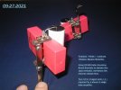
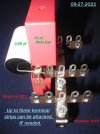
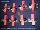
The finalized / vertically - elevated " RkM " ( cathode resistor bypass modules, holding 3 of the 5 film caps ) are fully developed.

Eight "RkM"s, enough for two stereo amps were constructed, finished today. The remaining two smallest film caps, for the highest frequencies, get attached to each tube's Cathode resistor directly ( Rk ), at the tube socket. This remaining two film cap bypass is ideal - done at the point-of-use, with almost zero lead length.


003 (3).JPG004 (3).JPG010 (2).JPG

Am not sure if a third Keystone 817 terminal strip will be needed, but photo above shows it.

Below, eight RkMs for two stereo amps . Mirror - imaged, back row versus front row.


017 (2) EDITED.jpg
020 (2).JPG


The " VAM " and " RkM " assemblies will nicely resolve previously- experienced space and parts access problems, when employing multiple film bypass capacitors. Especially in a stereo amp chassis. These two different modules enable parts to be easily accessible and serviceable.

It is a joy to have developed these two simple "Module " solutions.

NEXT : On to determining the best tube socket orientations, and overall chassis layout. Stay tuned.

Thank you very much - for looking.


Jeff
 
Last edited:
The power supply design topology outlined on 2-22-21 in this thread :

( https://www.hifivision.com/threads/...tly-coupled-audio-amplifier.82963/post-929069 )

has been changed ( about 8-2021) to a ( hopefully ) better-performing design.


- - - - - - - - - - - - - - - - - - - - -

The latest design takes extra power supply parts. The two recently-developed build Modules, ( designed for this crowded stereo amplifier- VAM and RkM ) , will free-up chassis space for the new power supply topology - to be installed and accessed for service.

The two most sensitive areas of this amp is the B+ feeding the plate resistor of the Input / Driver tube ( Ra ) , and (G2 ) the internal second grid of the Output Tetrode,. Both sensitive areas get the same design : a quadruple sectioned passive filter. Let me try to show it with a typewriter !!

Note, both of these filter chains get fed from the last capacitor that feeds the Final's ( Output ) tubes ( "C2" ). First of all, allow me to show you that ( initial ) output stage topology :

Main B+ Power Transformer > dual tube rectifiers > Main L1-6 Ohms / Main C1 / Main L2-6 Ohms / Main "C2" ( to both output transformers ) and to BOTH of the new quadruple filters, ......................... all fed from Main " C2 ".


( each "quad" B+ filter is - effectively : SHUNT 1, SHUNT 2, L1- one Ohm / C1 and L2- one Ohm / C2 ) . ( The L1 and L2 are those two tiny one Ohm hash chokes, seen on top of each "VAM". )

Either will be like this : Here we are :


............................................................................> Second SHUNT Left Channel >( "VAM" ) 15uF + L1 / C1 / L2 / C2 > ( feeds Ra Left ( or G2 Left )
Main "C2" > Pre SHUNT One, shared L-R ( split to each channel, see above and below )

..........................................................................> Second SHUNT Right Channel > ( "VAM" ) 15uF + L1 / C1 / L2 / C2 > ( feeds Ra Right ( or G2 Right )


This above filter, fed by MAIN
" C2" is built twice in the stereo amp, once for the Driver tubes' Ra, and once for the Finals' tubes' G2.

How confusing is my explanation? Please, only those F.M.s who can follow it, kindly leave a " thumbs up " or " like" at the bottom of this post. There may not be adequate room for all of the thumbs down . :)

I am anxious to hear this. For the record, a usual tube amplifier would use one resistor and one cap, called a R/C decoupling section.

" In the end, we all listen to a modulated power supply....how good is it ? "

Jeff
 
Last edited:
The power supply design topology outlined on 2-22-21 in this thread :

( https://www.hifivision.com/threads/...tly-coupled-audio-amplifier.82963/post-929069 )

has been changed ( about 8-2021) to a ( hopefully ) better-performing design.


- - - - - - - - - - - - - - - - - - - - -

The latest design takes extra power supply parts. The two recently-developed build Modules, ( designed for this crowded stereo amplifier- VAM and RkM ) , will free-up chassis space for the new power supply topology - to be installed and accessed for service.

The two most sensitive areas of this amp is the B+ feeding the plate resistor of the Input / Driver tube ( Ra ) , and (G2 ) the internal second grid of the Output Tetrode,. Both sensitive areas get the same design : a quadruple sectioned passive filter. Let me try to show it with a typewriter !!

Note, both of these filter chains get fed from the last capacitor that feeds the Final's ( Output ) tubes ( "C2" ). First of all, allow me to show you that ( initial ) output stage topology :

Main B+ Power Transformer > dual tube rectifiers > Main L1-6 Ohms / Main C1 / Main L2-6 Ohms / Main "C2" ( to both output transformers ) and to BOTH of the new quadruple filters, ......................... all fed from Main " C2 ".


( each "quad" B+ filter is - effectively : SHUNT 1, SHUNT 2, L1- one Ohm / C1 and L2- one Ohm / C2 ) . ( The L1 and L2 are those two tiny one Ohm hash chokes, seen on top of each "VAM". )

Either will be like this : Here we are :


............................................................................> Second SHUNT Left Channel >( "VAM" ) 15uF + L1 / C1 / L2 / C2 > ( feeds Ra Left ( or G2 Left )
Main "C2" > Pre SHUNT One, shared L-R ( split to each channel, see above and below )

..........................................................................> Second SHUNT Right Channel > ( "VAM" ) 15uF + L1 / C1 / L2 / C2 > ( feeds Ra Right ( or G2 Right )


This above filter, fed by MAIN
" C2" is built twice in the stereo amp, once for the Driver tubes' Ra, and once for the Finals' tubes' G2.

How confusing is my explanation? Please, only those F.M.s who can follow it, kindly leave a " thumbs up " or " like" at the bottom of this post. There may not be adequate room for all of the thumbs down . :)

I am anxious to hear this. For the record, a usual tube amplifier would use one resistor and one cap, called a R/C decoupling section.

" In the end, we all listen to a modulated power supply....how good is it ? "

Jeff
Because of this confusion, I preferred a monoblock.
 
10-01-2021 .............................. PHOTO UPDATE / PROGRESS REPORT


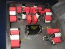
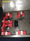
Test fitting of the newly developed multiple film cap modules, inside the new STEREO chassis. Very happily to me, it all fits inside neatly.

Now to lay out the main Power Supply components. One must thoughtfully consider lead lengths and fields.

Then, mounting holes for tube sockets, and off to the Powder Coating shop, prior to final wiring and assembly.

These new Modules make the stereo amplifier ( with all these not-really " extra " parts ) viable , both for amplifier construction and any sort of future below-chassis work needs.


016 edited.jpg

013 edited.jpg

021 edited.jpg

009 edited.jpg

019.JPG


On the extra-heavy-duty ( 12 gauge steel ) mounting bracket - for the 320 VA R-Core main power transformer, I have devised a new simple double vibration deterrent mounting scheme. The bracket itself, is double isolated with brass pyramids. Photos coming-up soon. Stay tuned.

Thanks for looking and following along.

Jeff
 
Last edited:
Historical Information :

Can we name some vintage USA tube amps, that employed dual 5U4G rectifier tubes - like this thread's new 2021 SE 6005 amp does ??


1) McIntosh M-60 monos, ...........their better-performing models of that era. ( Better than a Mc 275 . )


2) Fisher 50 AZs.......lovely, mono.

and


3) ALTEC 345A, stereo ............highly collectable, all Peerless iron, good sounding. Here it is below:


ALTEC 345A AMP SCHEMATIC, Save, USE, EXPLAINED 1.jpg

And a die hard Audiophile :

................................................fisher005.jpg
 
Last edited:
10-03-2021 ........................................ PROGRESS PHOTOS

Developed a new simple one - bolt attachment module today.

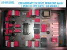
These enable mounting the large 50 Watt B+ SHUNT Power resistors wherever it seems best to position them inside the chassis. All this is used for extra-B+ filtering to the Driver tube and to Grid #2 of the Output tube. Both these circuit positions are super-sensitive to the cleanliness of their B+. This is done strictly to obtain outstanding amplifier performance.

This was gratifying to conceptualize over the last 48 hours, and build from scratch today.

033 edit.jpg025edited.jpg012 edited.jpg038 edited.jpg

Thanks for looking. I am pleased with this arrangement. More to do ! All is designed for high reliability, and is super conservatively operated . eg : These 50 Watt ARCOL HS resistors have a 1250 VDC Manufacturer's rating, and the B+ is 460 VDC. Many of the WIMA film power supply caps, ( shown in above-posts on this page ), have a lifetime use rating of 300,000 hours. That is over 34 years, of continuous operation.

Jeff
 
Last edited:
10-05-2021 .............. UPDATE

After doing all that work two days ago, to get those ARCOL HS 50 Watt resistors mounted onto Keystone 1569 Board Brackets, I have now decided to scrap that entire idea. ( This is all "part" of any careful amplifier development process. )

I just didn't like the way they fit into the amplifier.

Instead, yesterday I spent time having the ARCOL 50 Watt resistors be direct-to-the-chassis mounted. It is an additional 12 Watts the chassis will have to " sink ". Resistor positions are spaced to avoid chassis hot spots and to minimize resistor- to -resistor field reactions. The new chassis is large enough to do this.

One other thing, the capacitors will last the longest if they are kept cool.

The four main WIMA power supply caps ( 30 uF, 80uF, 50 uF and 50 uF ) will be mounted individually on spaced sheet metal " shelves "or " platforms " , 1/4 of an inch above the newly " resistor-heated " chassis floor.

Besides cooling and thus enhancing long term ( decades ) reliability of the film caps, wiring can now be freely routed below any capacitor, in the 1/4 inch open space beneath it. Win - Win, ..... if one is willing to do the extra work. Four WIMA capacitor platforms need to next be made-up, in the next day or two, including drilling and tapping 16 more holes ( 4-40 ) into the 14 gauge steel.

Hands and fingers have already gotten " beaten up " and bloodied. Carefully : measure twice, then cut or drill once.

Jeff
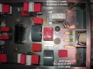
002 (3)  EDITED OK.jpg


004 (2) EDITED EXCELLENT CLOSE.jpg

Note : C2 Bypass GTO is positioned right between both Output transformer access holes of the chassis, for minimal and equal length feed of instantaneous pulsed music information.
 
Last edited:
LAYOUT, LAYOUT, LAYOUT .......................... 10-05-2021

The two layout photos ( in the above post ) pleased me on many levels, and I also liked its looks and symmetry.

However, two slightly different layouts have since come to mind today. I have not decided on which of the three to finalize upon, design-wise.

Here pictured below is OPTION 2 : The L2 choke was moved from the one long vertical wall, and brought closer to the other power supply components.


019 EDITED.jpg

020 EDITED.jpg

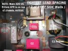
After looking at OPTION 2 photos ( above ) for awhile, one might ask, why not remove the 5VCT R-Core 5U4G Filament transformer, from it's side wall mounting ( NOT PHOTOGRAPHED )?? Why not bring it in closer, tighter-in towards the other supply components in the center of the amp ??

SO, below is the very very compact OPTION 3.

The only thing I do not know is how much fields will interact in this third option. R-Cores have about one tenth the radiated field of conventional E-I transformers, and the main R-Core power transformer sits on the top of the chassis / vertical, and should likely pose no problem. vertical. Option 3, moving the R-Core 5U4G filament transformer closer-inwards -( off of the side wall ), may work well.
I will show this to my Audio Mentor, Mr. Dennis Fraker, and seek his opinion.


031 (2)  EDITED BEST OPTION THREE.jpg

If I could get away with the tight spacing, field wise, I believe it could be the best performing choice. How will this Option 3 " look and feel " in a day or two ?? No more chassis hole drilling and tapping, until it is decided between these three layout options. If anyone has advice, feel free to express yourself...here or in a P.M. , nicely.

Thanks for looking. Matters like this above are a BIG deal, when seeking improved performance. The choice will soon be resolved ! Personally speaking, just three days ago I was terrified - that I would perhaps not develop a reasonable layout, being that it was a stereo amp with many parts.

Jeff
 
Last edited:
Looks nice!

Imo, the L1 is way to close to the resistors. The flux lekages from the L1 could interact with them. Try putting a shield inbetween them to avoid this. An aluminium wire- mesh could also be good enough. The mesh should be earthed. Or if possible encap the L1 in a metal case or something similar.


OK Hari, good point. Let us do this simpler than a shield.

By removing the L2 choke off of the left vertical chassis wall ( Option 2 ) , and the 5U4G filament XFR off the right vertical wall ( Option 3 ) , we can relocate many 50 Watt ARCOLS on those vertical chassis wall spaces. The mounting spaces become "freed up" - on either side of the chassis.

I will consider doing this on 10-6, but only when I am fresh and rested. We shall call relocating the resistors " Hari's Option 4 ".

Since the Option 3 photo was posted, I have moved the C1 Bypass GTO to be 1/2 inch closer to the chassis center, and the L2 choke 1/2 inch away from the center, to lessen possible field interactions between these two large power supply chokes.

In our filtering, the first choke, L1, has large current spike fields associated with it. This is because it is ( on purpose, to get low DCR ) less than textbook " Critical Inductance " rated....( thank goodness ). L1 is a Hammond 159ZA, with a generous 1 Amprere current rating, so it does a fine job with current spikes in the L1 position after a break-in of 75 hours. However, the 159ZA's use requires there always be a similar L2/C2 topology in series with L1/C1. L1 and L2 must be the same to avoid audible skews. Finally, we certainly want a choke input filter - that a 5U4-type rectifier "sees", not a capacitor.

We always use two sections of filtering " L1/C1/L2/C2 " to the Output stage. As you have found out Hari, these 6 Ohm 159ZA chokes perform wonderfully, especially when we combine them with our use of GTO bypasses and really good wiring to the Output stage.

Thank you very much for helping .

Jeff
 
Last edited:
Status
Not open for further replies.
Wharfedale Linton Heritage Speakers in Walnut finish at a Special Offer Price. BUY now before the price increase.
Back
Top