Restoring a vintage HMV Garrard turntable

atharva

Active Member
Joined
Jul 29, 2012
Messages
217
Points
43
Location
Pune
Hello everyone,

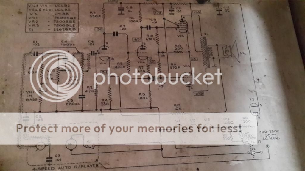
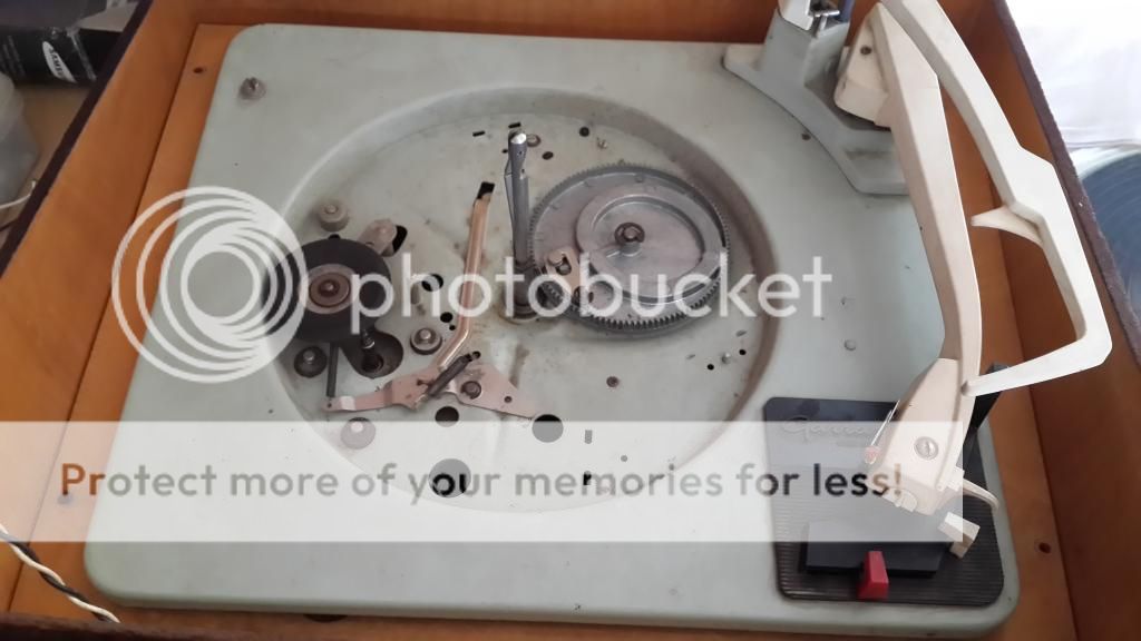
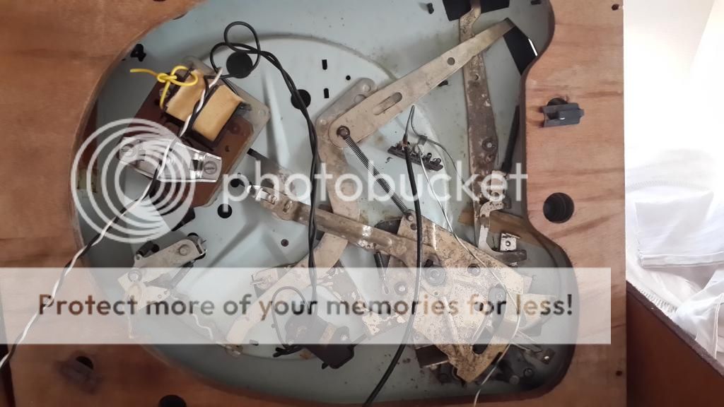
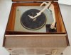
One of my dad's friend asked if I could take a look at his old HMV Garrard turntable and see if it could be fixed. He was very nostalgic about it so I thought I'd give it a shot. It is a mono TT with built in vacuum tube amp. FM Om Mishra was kind enough to help and after some investigation we found problems with following parts.

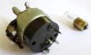
1. 1M Ohm Log Volume pot + On-Off switch 2 Pole (2 Amp 250V)
2. GE NE51 Neon Bulb (From the net seems replacement could be B1A 125 volts)
3. 350 Ohm 25 Watt wire wound ceramic resistor.

I checked the local market (Pune) but they don't have them. Would really appreciate any help in procuring these. I've attached pics of the volume control and neon bulb.

Regards and thanks in advance.
 

Attachments

  • HMV_Parts.jpg
    HMV_Parts.jpg
    13.2 KB · Views: 279
  • HMV_Garrard.jpg
    HMV_Garrard.jpg
    15.3 KB · Views: 277
What a lovely piece of vintage equipment, all the very best for your restoration.

From which part of the circuit is that 25 watt resistor from? If its from the power supply, and if its used as a drop down for the tube filaments, please be careful as the amp may have a live chassis.

By the way, you have a Garrard Auto-slim record changer in there. That's one of the Garrard work horses from radiograms and record players. Would require some simple lubing, maybe a new stylus but nothing else. These things are built to last a couple of life-times.

The voltage rating which you have mentioned for the bulb, was it printed on the bulb? If yes, then you definitely need to be careful about the chassis. There are broadly 2 types of tube-based radios and record players, namely AC and AC/DC. AC equipment had mains auto-transformers while AC/DC equipment had the drop-down resistor. The lamps that light up indicators and dials in these AC sets were usually rated at 6.3 volts, which was similar to the tube heater voltage ratings. The rating you mentioned relates to an AC/DC filament system with all filaments and the dial lamps connected in series. These are all assumptions but some pictures of the actual inside can throw more light (for interest's sake).

Would be nice to see the wood-work restored as well :)
 
Last edited:
Hello Reuben,

Thanks for the encouraging words.

Yes, the resistor seems like for the drop-down for the filaments. I'm only opening it under Om's watchful eyes :) But thanks for the warning.

Really hoping someone can help with the parts.
 
A good place to search will be in the older spare parts shops that have been around for a long long time. Also enquiring with old-time radio-repairers would help. Many many years ago, we used to own the AC/DC version of the famous Ferguson 454 radio and its drop down resistor blew off. I remember Dad getting a friend in Chennai to search through Moore market (not the current one but the original one) and they managed to get the spare. On another occasion, I recollect him salvaging a drop down resistor from an old Orient pedestal fan speed controller (not the electronic type but the old push-button type) and adapting it as a filament drop-down resistor for another radio repair job.

On another note, if the dial lamp fuses or any of the tube filaments blow out, the whole radio usually goes dead as the filaments and dial lamps are wired in series :)

With AC/DC radios, always use a 3-way AC mains plug. Never reverse the polarity or the chassis will become live. A good form of protection is to use an isolation transformer.
 
Thanks Reuben,

I had taken pics before I lugged this heavy TT from my place to Om's. Now I'm driving with it in my trunk :) I will try to post some pics of the insides.

You are spot on with your analysis. Forgot to mention that the circuit is printed and pasted inside and in good condition. There are 2 tube diodes so we suspect AC/DC too. Yes the filaments are in series I think. Will watch out for the polarity.

Unfortunately I don't know any such shops in Pune. Am hoping someone here can either share a phone number or help source these. I could find the resistor and bulb online but shipping to India is a killer.

If you can share the valve details, I can probably suggest the resistor value to use. I would assume your record player has a UCL82 or UCL86 valve for the audio stage and a UY85 or likewise for rectification.

Here is an example of a typical circuit of such a AC/DC record player. This version has a ceramic source driving an output stage directly:

circuit.jpg


From the circuit, it is evident, why the chassis becomes live when the AC mains Line and Neutral pins are reversed :)
 
Last edited:
I just went over and got the TT from the car trunk :)

Here is a pic of the circuit. The resistor value is printed as 350 Ohm but we are not sure of the wattage. So we thought it safe to use a 25W.

HMV-Circuit_zpso5ctkbaq.jpg
 
The UCL82 tube comes with a 50 volt heater filament, while the UY85 tube comes with a 38 volt heater filament. Both are rated at around 100ma. So if you are looking at 2 x UCL82 + 1 x UY85, the filaments have to be fed by around 138 volts. The key resistor here is R15, which is 1090 ohms. This is normally a rheostat rated at around 25 watts. You will have to adjust the tap till you get an output of 138 volts. If you can post some pictures of the inside, we can probably help with more info.

From the spares requirement mentioned, you should be able to easily find the bulb and the resistor. The pot can be got from old radio shops or can be bought online (which is the expensive route).

The circuit itself is a clever push-pull design. By using half of the two UCL 82 tubes for the output and the other halfs for the driver stages, the designers have cleverly kept the design down to 2 valves to save on the cost front. In normal circumstances, one would use two UL84s tubes and one UCC85 tube. The two push-pull UCL82s should deliver around 6 odd watts into 3 ohms.
 
Last edited:
Yes, we also realised that the R15 is key here. I will check the voltages as you mentioned. Unfortunately I can't make the next move unless I get above parts.

I was certain of finding the bulb and resistor easily. But no luck. If anyone visits bigger electronic markets like Lamington Road in Mumbai I would really appreciate if you can check the availability of these parts for me.

Also Chennai is a good place to search for such parts :)

Local sourcing is the less expensive option, but if you turn up empty-handed, there is always the western world. All your mentioned components could be easily procured from vendors of vintage radio spares in the UK or US, however you'll end of paying an average of $10-$15 for each component, plus shipping extra.
 
Last edited:
If I don't get the bulb can't I put a resistor in its place? From the net The NE51 seems to be rated as @ 110 - 115V 0.3 Amp. Will a ~ 400 Ohm 35W resistor do?
 
I would assume that the impedance of the bulb would be just under the 100 ohms mark. In theory, yes using a resistor shunt instead of the bulb should work, but not sure about the practical application. Perhaps experienced forum members like omishra can help here. From the circuit, the interpretation that I get is, by placing the bulb where it is, in the circuit, the designer of the circuit intended it to double as a fuse as well.
 
Will check. The cartridge on this is also broken. The name is "Sonotone". Which cart can I use as replacement? Where can I get it?
 
Will check. The cartridge on this is also broken. The name is "Sonotone". Which cart can I use as replacement? Where can I get it?

Is the cart broken or is the stylus broken? If the stylus is broken, you are very unlucky, I had a mint sonotone stylus which I gave away with my Garrard RC210 changer to a FM. If its only the stylus, you can probably contact him and check if he's willing to sell it or gift it to you :)

The interesting aspect is that I restored the Garrard RC210 and replaced its original sonotone cart with an EEI CS2000 stereo cart. So he may have the Sonotone stylus lying around :)
 
I made some progress.

1. Confirmed that the motor works.
2. Removed platter and checked condition of idler wheel. Looks in good shape. Rubber is soft.
3. The platter spins and the speed change (16, 33, 45 and 78) works too.

The mechanism definitely needs cleaning and greasing. I suppose I should use White Lithium Grease for this?

Some pics attached

HMV-top_zpsx2vogywf.jpg


HMV-Idler_zpsyj5r06g2.jpg


HMV-machine_zpspsalyzhw.jpg
 
The mechanicals are looking great, yes, the white grease will work but limit application, don't use like butter :) Also clean properly before greasing. Once greased, cover properly to avoid dust. Run a check on the speed, stick a small piece of take on the platter rubber mat, and a corresponding piece on the chassis outside the platter, check each speed (you should have 78 revolutions in a minute for 78 rpm, 45 per minute for 45 rpm and so on. I take is that it will be accurate :)

On another note, Garrard turntables with the red and white lever knobs are rare and also, they look good.
 
I got the grease and tried applying it on one joint. I did apply it like butter :) Will remove the excess. I feel I have to remove the C-clips to get it between the joints. A bit nervous with that since there are springs and what not and am worried I won't be able to put it back together. Any tricks to get it in without removing the c-clips?

While removing the c-clip on the platter spindle I've already managed to lose it between the metal platter and black mat which is stuck on it.
 
The Marantz PM7000N offers big, spacious and insightful sound, class-leading clarity and a solid streaming platform in a award winning package.
Back
Top