TDA7293 parallel design DIY

hydrovac

Well-Known Member
Joined
Jan 10, 2007
Messages
1,205
Points
113
Location
Hyderabad
As part of my home theater build, have decided to go for 3 way actives for front LCR so, need to build 9 power amps for fronts and 8 amps for surrounds to pair up with my Sherbourn PT-7020A pre/pro.

I needed something as easy, but more powerful. This is when I and my friend John found the datasheet of TDA7293. This IC can run up to 100V, low distortion, and can easily be paralleled.

I have been looking for a source of PCBs using parallel TDA7293s there are not many out there that you can buy. We then decided to do our own PCB. Our schematic is almost the same as in datasheet... the board layouts in the datasheet are flawed and little clumsy we used them only as guidance with component arrangement on our PCB after few futile attempts to route the board with minimum jumper count.

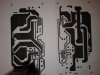
Pin out on TDA7293 is tricky, so single-sided board is difficult to draw, and in the end contains more jumpers between lines than tracks so, this one is made as double sided.

I thought it would be good to share my project with the community maybe someone finds it useful.

Tentative double side PCB layout, top and bottom sides have to check pitch and spacing with actual components we have before fabricating the PCB.
 

Attachments

  • 20150206_122826.jpg
    20150206_122826.jpg
    16.1 KB · Views: 476
Last edited:
What about this? slight modification will serve the purpose, I think. All the best with the Project. Pls keep updated about the progress. In the mean time, why chipamps when exxellent discrete designs are available?
 

Attachments

  • 7293.jpg
    7293.jpg
    34.7 KB · Views: 445
Having sampled the superb sounding first version of this, I'm very curious to know how this revised design sounds. Would be watching the progress keenly.
 
Last edited:
I have heard bridged TDA7294 and it sounded pretty good (being used as a sub amp driving 12" JBL in a shop). I bought one which has being lying around unused for a year or so. It's seems like a simple circuit.
 

Attachments

  • Image1250.jpg
    Image1250.jpg
    15.8 KB · Views: 412
  • Image1253.jpg
    Image1253.jpg
    17.9 KB · Views: 413
Good attempt, what are the dimensions of the PCB?
@ goldyrathore,
The actual finished size of the double sided PCB would be 17.5 X 8 cm.


What about this? slight modification will serve the purpose, I think. All the best with the Project. Pls keep updated about the progress. In the mean time, why chipamps when exxellent discrete designs are available?
@ diesel engine,
Hello, delusion knows no bounds there are quite a few discrete amps out there and a variety of opinions around these chip amps now the real plain question that is unanswered is what type of amps one should build??... I'd worry instead about whether the amps do the job you have in mind for them - I'd not worry too much about the ingredients, technology - fully discrete or chips implementation is (almost) all.
Just trying out some different amp designs... Isnt the point of DIY and homebrew to learn about stuff and try things out?

Your mileage may vary You are all welcome to opinions, have a look, build one have a listen, then make your own mind up;) I guess it is sometimes is hard to say "A" is better that "B" cause there are usually a lot of variables thrown around.
If you leave your prejudices at the door and come in with an open mind and use your imagination, Im sure we'll all learn something new.
Welcome to the chipboard...:D


Having sampled the superb sounding first version of this, I'm very curious to know how this revised sounds. Would be watching the progress keenly.
@ captrajesh
The amp you auditioned in my HT is a single chip version of TDA7293 thanks for visiting my humble abode capt.:)


Wish you were in kolkata or i was in bangalore, that would have made auditioning possible.
@ saheb11123
For your kind info, I am based in Hyderabad.:eek:


Revised and final layout, film and silk screen will be sending out for fabrication.

isqy3iw.jpg


@ kaushik
I don't want to do another PhD in PCB making... Been there, done that! now i only outsource them:D

Just received the double sided, 1.6 mm thick prototype PCBs... looking nice:) very few components to sort out and to populate the board, maybe in less than 20 minutes ;):)

Vj4a67w.jpg

R0FTXHe.jpg

5wLlX2M.jpg

tU3mjeL.jpg


Cheers!
 
@ kaushik
I don't want to do another PhD in PCB making... Been there, done that! now i only outsource them:D

Just received the double sided, 1.6 mm thick prototype PCBs... looking nice:) very few components to sort out and to populate the board, maybe in less than 20 minutes ;):)

What P.S. are you going to be using?

Moderator's note: Quoting entire posts, especially images consumes precious Bandwidth and have been removed. Kindly avoid doing so.
 
Last edited by a moderator:
What P.S. are you going to be using?

@ keith_correa,

I'm not entirely clear from your question, but I take it you are asking about rail voltages... that's a good debatable murky topic.;)
The simple answer is straight unregulated... will come to that later:)

In the mean time... pl take a look at the populated boards:D

QL4CQbr.jpg


8mk6mkU.jpg


oSCXpJO.jpg
 
Last edited by a moderator:
yes i can understand pcb making @home is a timewaster
yup experimenters like me have to do while fiddling some designs
final designs obviously goes to PCB FAB guy
nice going so far ,i prefer RED masks my FAB guys giving me 4 color options

-the tiny resizer (drag drop type) you can use to reduce pic size
will help many people to browse the pics
 
Good looking! :thumbsup:
Thanks Sarith!
Yes indeed, it is a simple circuit. In your previous post, you have mentioned about TDA7294 bridged amp... can you share the power supply details and the load driven... heat dissipation on the heat sinks?
BTW I noticed the brand/model on the PCB is masked out any specific reason, such as copyright, trade mark, or IP?
Cheers!


yes i can understand pcb making @home is a timewaster
yup experimenters like me have to do while fiddling some designs
final designs obviously goes to PCB FAB guy
nice going so far ,i prefer RED masks my FAB guys giving me 4 color options

-the tiny resizer (drag drop type) you can use to reduce pic size
will help many people to browse the pics

Considering the way you phrased it, "timewaster", it would seem you already don't want to do it, and so your own personal preference may be to have them professionally made.:)

By all means experiment, IMHO... for low quantity fabrication, this method can save you some time and help you stay within your budget but remember that cutting corners can easily reduce quality & waste time. I don't even bother with it for personal projects anymore.
There are just too many inexpensive quick-turn places that can do it better than you can ever hope to. I use an outfit that specializes in small quantities you don't even have to send them Gerbers as they will work with whatever native software you use (I send them *.brd Eagle files). I usually get boards with solder mask and silkscreen in quantities of 3-4 and have never spent more than their worth interestingly though, I have not had to throw out any prototypes.:D

Solder mask is taking on a rainbow of colors I am just wondering what is the significance of solder mask color... it is purely a function of designer preference, and whether the person paying for the boards is willing to foot the bill for custom solder mask colors. In fact, the aesthetical/cosmetic part isn't important for me...:indifferent14: the stuff should protect the board from oxidation and corrosion; I prefer the traditional de-facto green.;)

Ok, further on the project:
I found an old enclosure which can accommodate the amp board, heat sink, power transformer rectifier and filter capacitors the trafo is a 32-0-32 250VA... searches seem to suggest this is the absolute upper limit for TDA7293 setup.

The heat sink I have, also cannibalized from a fried receiver is 11" wide, 3.25" tall, and sports 22 fins, each being 2" long. It weighs about 1.5 kg., give or take. Assuming I can get a decent enough thermal contact for each IC, does this heat sink sound like it will have enough mass to support two TDA7293s? (Yeah, I know there's a lot of thermodynamics data that would be needed to get an accurate reading on whether/how well this 'sink will work, but all I can give are raw measurements.)

For the smoothing circuit, I'm using quad 1200uF capacitors (low-ESR caps designed for power-supply filter applications) per board, in addition to the dual 6,800uF caps in the supply rails. Will this be adequate at least initially, or would it be wise to snag a few 10,000uF monsters to add to the power filtration?
Thats all I can think of right now more as I come up with it.

Resized images::D
sgl5z1I.jpg


xREnlJe.jpg


TS5KQmm.jpg


znmMpn0.jpg
 
Thanks Sarith!
Yes indeed, it is a simple circuit. In your previous post, you have mentioned about TDA7294 bridged amp... can you share the power supply details and the load driven... heat dissipation on the heat sinks?
BTW I noticed the brand/model on the PCB is masked out any specific reason, such as copyright, trade mark, or IP?
Cheers!

You're welcome! I haven't used this amp board yet. I bought it from a local electronics shop few districts north. The name is 'effect'. Never heard of it before and haven't seen another board till date.

I masked it because of not so known brand name. I bought it some time ago and is lying unused. I have dmos 5 channel amp board too. I have upgraded the caps from polyester to mkp and power electrolytic to Keltron.
 
Get the Wharfedale EVO 4.2 3-Way Standmount Speakers at a Special Offer Price.
Back
Top