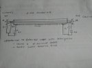
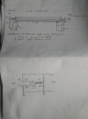
I had come across this interesting cable wiring last year when i was searching for my DIY tube amplifier built but did not pursue them as i was not keen at that point in time. Now, as i have settled with my DIY tube amplifier and DIY OB speakers (hopefully) i thought of pursuing them now. But unfortunately i could not trace that article as i did not save the link or copied it elsewhere. I have drawn the below schematic from what i could recollect and am planning to build them asap.

As you can see from the schematic, the electrons (negatively charged e-) on the hot and cold terminals will flow from the input to the output of the cable in one direction as the shield is given a +ve polarity with a battery. The value of the resistors will depend upon your pre-amplifier input impedance and the capacitor is used for allowing RF above 1MHz so that the shield itself dont behave like an antenna. Alternatively the capacitor also allow balance of the cable. The DC will not flow to the cables due to the presence of the capacitor but still have a +ve polarity to allow the electrons (RF) to get pulled toward it creating a direction for the cable. This will enable faster break-in of the cable.
IMO, you will not have to connect the battery for more than a month or a two after the direction of the cable is established. Also the battery will be never drained as their is no current flow anywhere. You should also notice that the H & C is give a battery -ve polarity to make the electrons -vely charged w.r.t. the shield.
This is still in concept stage and work for my coming weekend. Agreed its not a "Moorthy Cable" which has rave reviews in this forum. Hope it will be some where nearby.
Thanks for looking.


