You are using an out of date browser. It may not display this or other websites correctly.
You should upgrade or use an alternative browser.
You should upgrade or use an alternative browser.
300 watt Hi-fi power amp project.
- Thread starter hydrovac
- Start date

twidlerjohn
New Member
Great Build, hydrovac !
Any particular reason why you chose this design, which drives the output thru the collectors ? This implies gain by the output stage and therefore more feedback applied. These designs were popular in the era of high feedback (Which provide better thermal stability and lower steady state distortion, but today is looked on suspiciously for poorer sound ).
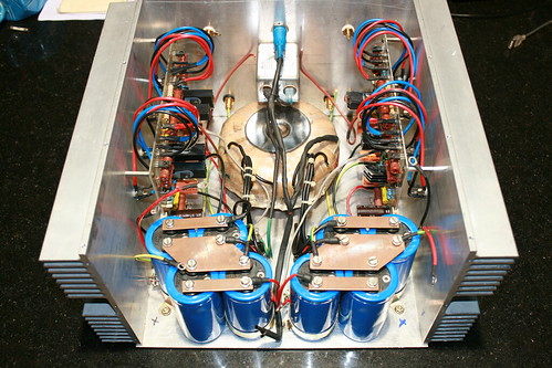
Love the attention you have paid to the Power Supply, including the Professional Grade Caps !
All the best.
Hi,
Let me introduce myself as the other 'partner-in-crime' in these audio ventures. You're right, gain at the output stage seems to have low esteem among the present generation of audio engineers! I am no expert to comment, but this is the third collector-coupled output stage scheme I have tried. The first one was during college days, when the Philips' BD-series were the only audio power transistors available in Madurai. At the time I had nothing to compare it with, but it sounded a lot more clear than a cinema theatre. So I never had a hangup on collector-coupled output stages.
In the present project (actually it is quite a few years old since we made the prototype), what attracted our attention was the symmetry of the circuit
and the easily available components, apart from a fairly non-obtrusive load-line protection circuitry. When we tested the first proto, we had a good reference to compare with - an Adcom GFA555. And our amp sounded far superior to the GFA555 - very transparent sound stage, free of the grainy sound the Adcom had. We tested it on about half a dozen speakers in hand (mostly built by us), and also compared with a Luxman integrated (I forget the model). Till now we have not heard a better amp than this. We use it with a preamp we made with OPA2134's, and till now haven't come across anything with better sound.
We never made any measurements so far, but once we get the oscilloscope, we should be able post some electrical performance info.
Thanks for the encouragements!
John
Hi Hydrovac,
I Did check Both the links, before posting here, asking you.
Maybe I am missing something ?
Can you please post here, the answer, or a link to the Specific page that provides an answer to my query ?
Sincere Thanks !
You have a very interesting point there. Poorer sound! Audio circuits have been around for many decades now, and the main costs are in the power devices and power supplies, Things should be as simple as they can, but no simpler than that. I think. It is very interesting that this simple circuit (and its countless variations) have "survived".
This statement gives me reason to think over these designs from time to time. Very nice for us "home builders". These components and transistors are very easy to find in every part of the world.
Not often designers think of that. Designs using unusual and new exotic transistors can be very difficult finding spares, if something goes wrong. Designs for DIYers should consider how a potential builder can get the comps easily.
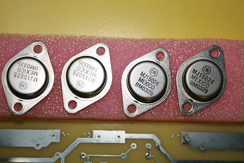
A common factor of very popular & successful amplifier-projects is that, they use semiconductors that belong to "the mainstream" of production, by BIG manufacturers.
So this looked good to us.
Regards
Krishna
sarith
Active Member
Hi all DIYers,
Building a 300 watt Hi-fi power amp, which we designed and prototyped few years ago.
Please follow the links for details.
310W Power Amplifier - diyAudio
310W Power Amplifier - Page 4 - diyAudio
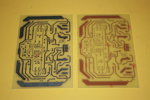
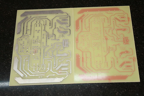
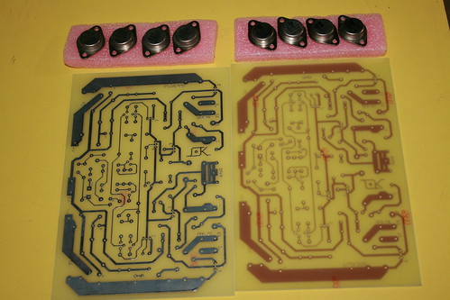
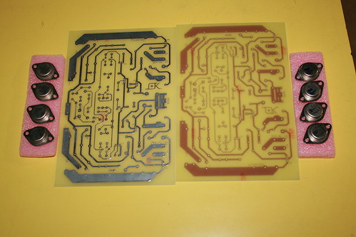
PCBs have been fabricated and gathering all components on hand.
Few pictures of the same.
IMG_4459 by hydrovac, on Flickr
IMG_4458 by hydrovac, on Flickr
IMG_4461 by hydrovac, on Flickr
IMG_4462 by hydrovac, on Flickr
IMG_4570 by hydrovac, on Flickr
IMG_4575 by hydrovac, on Flickr
IMG_4465 by hydrovac, on Flickr
IMG_4464 by hydrovac, on Flickr
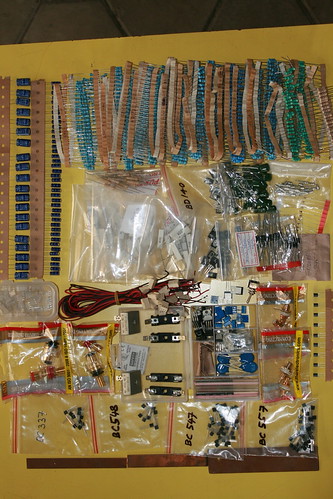
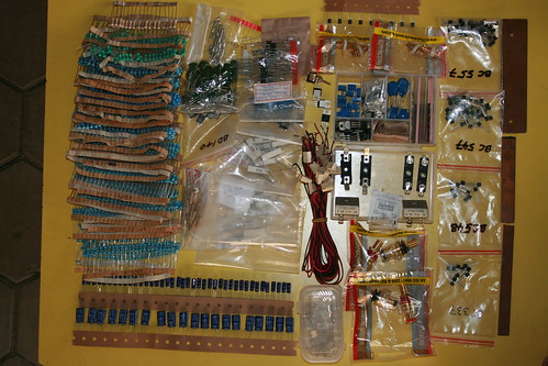

A treat to DIYer's eyes (like a candy shop to kids)
Hi friends,
Sorry for the long gap in my post as I was preoccupied with other commitments. In continuation to my earlier posts, here is progress in amp build.
Checking the DC rail voltages: Left channel, Right channel, both channels
IMG_4645 by hydrovac, on Flickr
IMG_4646 by hydrovac, on Flickr
IMG_4648 by hydrovac, on Flickr
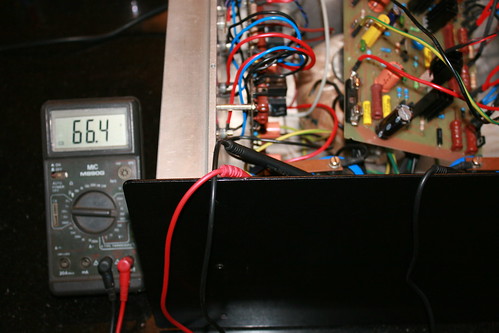
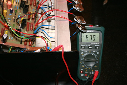
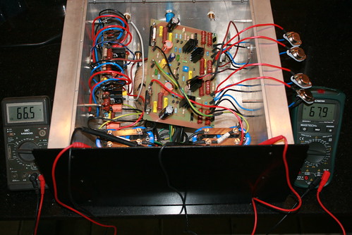
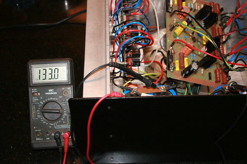
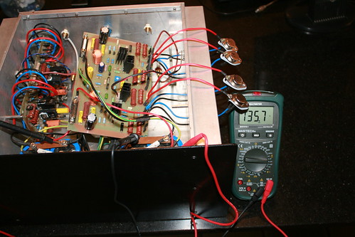
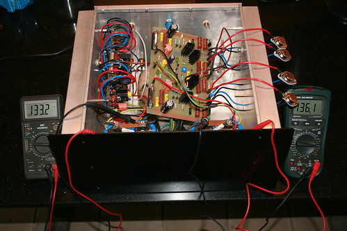
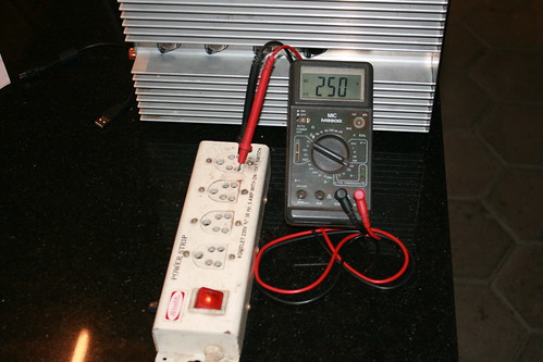
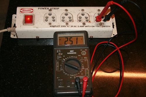
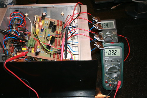
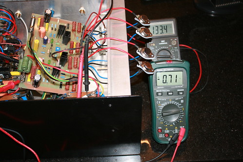
Checking full rail voltages: Left channel, Right channel, - Ve and +Ve rails
IMG_4652 by hydrovac, on Flickr
IMG_4653 by hydrovac, on Flickr
IMG_4655 by hydrovac, on Flickr
I am supposed to get around +62 and -62 volts DC on rails. The increase in reading is because of the mains input voltage (250 volts AC). Toroidal transformer winding is rated for 230 volts primary.
IMG_4682 by hydrovac, on Flickr
IMG_4686 by hydrovac, on Flickr
IMG_4683 by hydrovac, on Flickr
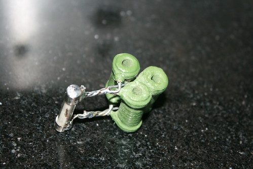
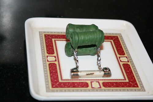
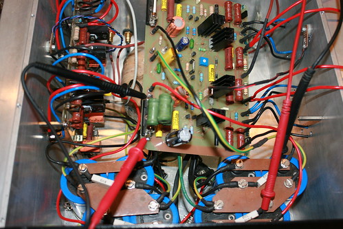
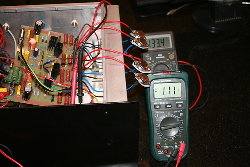
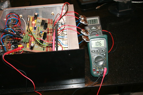
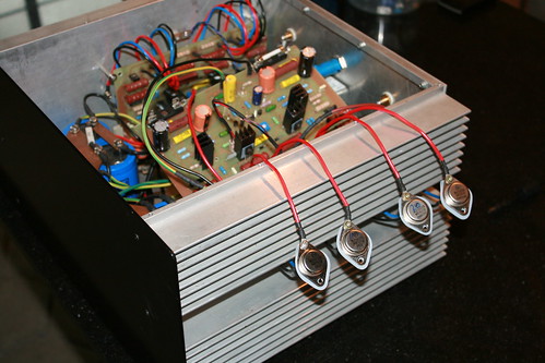
Setting the quiescent bias current for output stage:
Fabricated a 10 ohm 5 watt wire wound resistor suitable for the fuse holder.
IMG_4671 by hydrovac, on Flickr
IMG_4674 by hydrovac, on Flickr
Inserted in +Ve side holder and switched on the power. Adjusted the trim pot to get, 1.0 volt across the resistor.
IMG_4658 by hydrovac, on Flickr
IMG_4660 by hydrovac, on Flickr
IMG_4661 by hydrovac, on Flickr
IMG_4662 by hydrovac, on Flickr
IMG_4657 by hydrovac, on Flickr
IMG_4659 by hydrovac, on Flickr
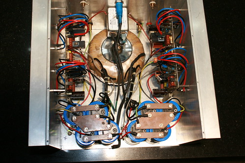
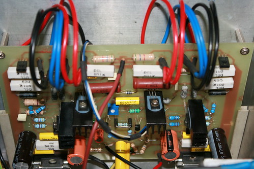
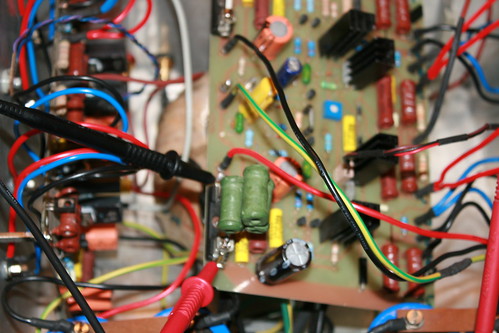
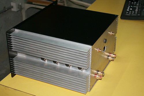
You can see the thermal sensing bias transistors mounted mid way between the power transistors on the heat sink. Good going so far.
IMG_4678 by hydrovac, on Flickr
IMG_4680 by hydrovac, on Flickr
IMG_4679 by hydrovac, on Flickr
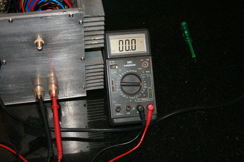
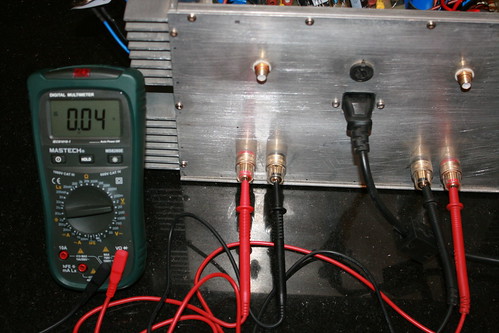
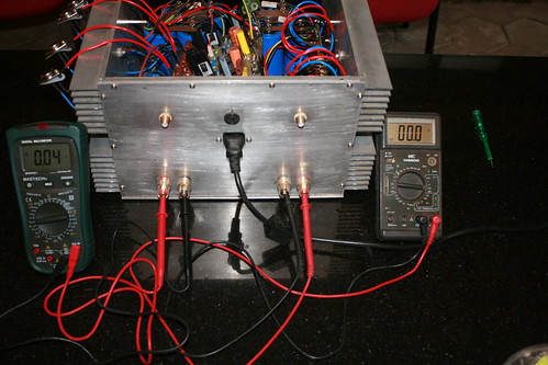
Now, looking at output side. Measuring the speaker output terminals for DC.
IMG_4669 by hydrovac, on Flickr
IMG_4668 by hydrovac, on Flickr
IMG_4667 by hydrovac, on Flickr
Left channel looks clean without any DC. But right channel is showing 0.04 volts. There seems to be a hitch somewhere. I will get back with updates after trouble shooting.
Thanks for looking and following the post.
Sorry for the long gap in my post as I was preoccupied with other commitments. In continuation to my earlier posts, here is progress in amp build.
Checking the DC rail voltages: Left channel, Right channel, both channels
IMG_4645 by hydrovac, on Flickr
IMG_4646 by hydrovac, on Flickr
IMG_4648 by hydrovac, on Flickr
Checking full rail voltages: Left channel, Right channel, - Ve and +Ve rails
IMG_4652 by hydrovac, on Flickr
IMG_4653 by hydrovac, on Flickr
IMG_4655 by hydrovac, on Flickr
I am supposed to get around +62 and -62 volts DC on rails. The increase in reading is because of the mains input voltage (250 volts AC). Toroidal transformer winding is rated for 230 volts primary.
IMG_4682 by hydrovac, on Flickr
IMG_4686 by hydrovac, on Flickr
IMG_4683 by hydrovac, on Flickr
Setting the quiescent bias current for output stage:
Fabricated a 10 ohm 5 watt wire wound resistor suitable for the fuse holder.
IMG_4671 by hydrovac, on Flickr
IMG_4674 by hydrovac, on Flickr
Inserted in +Ve side holder and switched on the power. Adjusted the trim pot to get, 1.0 volt across the resistor.
IMG_4658 by hydrovac, on Flickr
IMG_4660 by hydrovac, on Flickr
IMG_4661 by hydrovac, on Flickr
IMG_4662 by hydrovac, on Flickr
IMG_4657 by hydrovac, on Flickr
IMG_4659 by hydrovac, on Flickr
You can see the thermal sensing bias transistors mounted mid way between the power transistors on the heat sink. Good going so far.
IMG_4678 by hydrovac, on Flickr
IMG_4680 by hydrovac, on Flickr
IMG_4679 by hydrovac, on Flickr
Now, looking at output side. Measuring the speaker output terminals for DC.
IMG_4669 by hydrovac, on Flickr
IMG_4668 by hydrovac, on Flickr
IMG_4667 by hydrovac, on Flickr
Left channel looks clean without any DC. But right channel is showing 0.04 volts. There seems to be a hitch somewhere. I will get back with updates after trouble shooting.
Thanks for looking and following the post.
diesel engine
Active Member
Hi suraj,
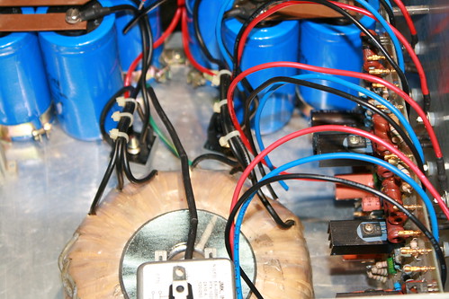
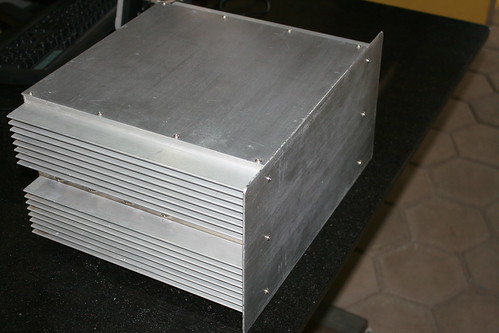
It is 2 mm copper sheet cut and used as bus bar.
Regards
krishna
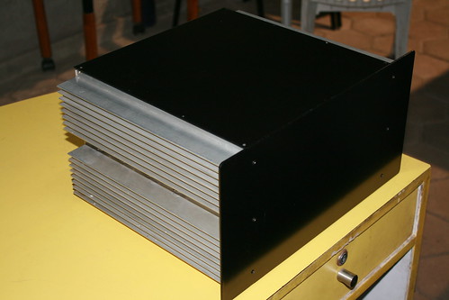
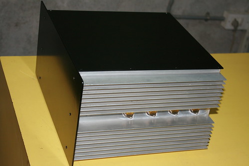
great build sir. where did you procure those 3mm(I persume) Aluminium sheets? who is the manufacturer? I have been looking for that for a long time.
Actually 40mv dc offset isnt that bad. I traced it to a slightly leaky cap. Replaced it and now it reads 1.5mv on right channel and 2.8mv on left channel, in 200mv range of multi meter.
My Dc offset is excellent and will not damage the speakers, but many say as high as 50mv is still OK.
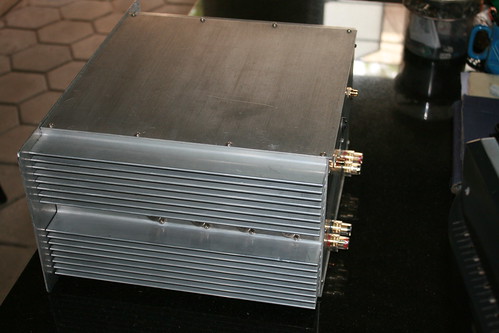
I connected a source and performed an extensive listening session. Must confess the amp has an amazing sonic quality.
IMG_4441 by hydrovac, on Flickr
IMG_4445 by hydrovac, on Flickr
IMG_4478 by hydrovac, on Flickr
IMG_4482 by hydrovac, on Flickr
IMG_4580 by hydrovac, on Flickr
IMG_4579 by hydrovac, on Flickr
IMG_4577 by hydrovac, on Flickr
My Dc offset is excellent and will not damage the speakers, but many say as high as 50mv is still OK.
I connected a source and performed an extensive listening session. Must confess the amp has an amazing sonic quality.
IMG_4441 by hydrovac, on Flickr
IMG_4445 by hydrovac, on Flickr
IMG_4478 by hydrovac, on Flickr
IMG_4482 by hydrovac, on Flickr
IMG_4580 by hydrovac, on Flickr
IMG_4579 by hydrovac, on Flickr
IMG_4577 by hydrovac, on Flickr
sarith
Active Member
Great job!
sashijoseph
Member
Excellent work..
Hydrovac,your builds are truly inspiring.
Hydrovac,your builds are truly inspiring.
Excellent work..
Hydrovac,your builds are truly inspiring.
Thanks sashijoseph.
Have few extra PCBs to spare....
We would like to share our experience of the PWA 300 with other enthusiasts with passion for perfection. We designed this minimalist amplifier to be durable, simple to operate while offering high fidelity life like sound equivalent to the original source and would recommend partnering this amplifier only with other products of outstanding quality.
When we set out to design this amplifier, our aim was to create a product most suitable for the reproduction of complex music and speech signals. Although we placed high emphasis on electrical characteristics, the single most important requirement is achieving an audibly superior sound, vivid spatial imaging and superb tonal clarity. The low noise floor (no hum or noise) improved the dynamics and accuracy of the tonal characteristics of instruments and voices significantly.
Although the average listening level is normally less than 10 watts, our design approach was to create an amplifier with ample reserve power at average listening levels, reducing cross-over distortion to extremely low levels. The amp has almost zero phase distortion far beyond the audio range resulting in perfect resolution and totally UN-colored sound.
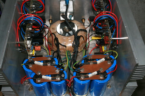
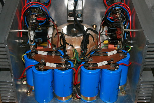
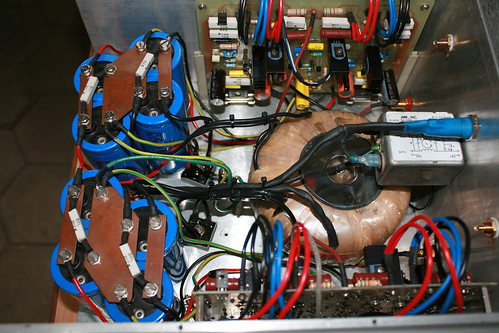
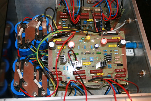
In order to obtain the full output power the supply transformer is rated at 45VAC 0 45VAC at 375VA (each secondary) providing +/- 64VDC on rails. Unlike many designs relying on the reservoir capacitors to supply peak currents, we prefer to have the raw power available from the transformer resulting in much faster transients. The filter capacitor is around 40,000uF 100V for each rail.
Although the amps specifications are moderate, when listening to it you will immediately experience the massive reserve power available and never have any cause of anxiety that something is going to give in, that one would when driving many amplifiers loud.
You will hear nothing but reality with no distortion at any level and we guarantee that this amplifier will divulge the best qualities of the equipment connected to it. Of course speakers, inter-connections and source does play a significant role in the final result. However, the choice of speakers and music is like your choice of fine wine, it is what you enjoy.
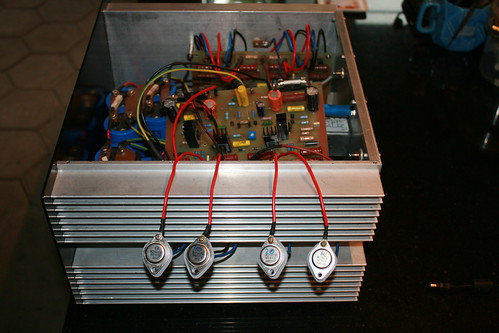
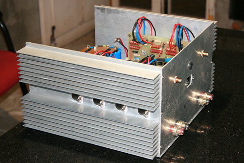
I have few extra PCBs to spare and willing to assist any wannabe DIYer on the forum interested in building this power amp. I am convinced that you would be as pleased and proud owning this amplifier as I am, never finding the need to upgrade as it will provide you with many of years of listening pleasure. It sounds great and has had it on the signal generator and scope and output seems nice and flat all the way. We must say a word of thanks to Sam for putting this design on the net. The output devices mounting arrangement works very well and have added fan cooling that kicks in at 40 degrees.
Amplifier Specs:
Maximum Output: 200 watt rms into 8 Ohms, 300 watt rms into 4 Ohms
Audio Frequency Linearity: 20HZ - 20KHZ +/-0.5dB
Closed Loop Gain: 32 dB
Hum and Noise: -105 dB (input short circuit)
Damping Factor: 65 Output Offset Voltage: Less than 5 mV (input short circuit)
Phase Linearity: Less than 13 0 (10 Hz - 20 kHz)
Harmonic Distortion: Less than 0.007% at rated power
Distortion: Less than .009% at maximum power
Thanks for following the post and encouragement.
We would like to share our experience of the PWA 300 with other enthusiasts with passion for perfection. We designed this minimalist amplifier to be durable, simple to operate while offering high fidelity life like sound equivalent to the original source and would recommend partnering this amplifier only with other products of outstanding quality.
When we set out to design this amplifier, our aim was to create a product most suitable for the reproduction of complex music and speech signals. Although we placed high emphasis on electrical characteristics, the single most important requirement is achieving an audibly superior sound, vivid spatial imaging and superb tonal clarity. The low noise floor (no hum or noise) improved the dynamics and accuracy of the tonal characteristics of instruments and voices significantly.
Although the average listening level is normally less than 10 watts, our design approach was to create an amplifier with ample reserve power at average listening levels, reducing cross-over distortion to extremely low levels. The amp has almost zero phase distortion far beyond the audio range resulting in perfect resolution and totally UN-colored sound.
In order to obtain the full output power the supply transformer is rated at 45VAC 0 45VAC at 375VA (each secondary) providing +/- 64VDC on rails. Unlike many designs relying on the reservoir capacitors to supply peak currents, we prefer to have the raw power available from the transformer resulting in much faster transients. The filter capacitor is around 40,000uF 100V for each rail.
Although the amps specifications are moderate, when listening to it you will immediately experience the massive reserve power available and never have any cause of anxiety that something is going to give in, that one would when driving many amplifiers loud.
You will hear nothing but reality with no distortion at any level and we guarantee that this amplifier will divulge the best qualities of the equipment connected to it. Of course speakers, inter-connections and source does play a significant role in the final result. However, the choice of speakers and music is like your choice of fine wine, it is what you enjoy.
I have few extra PCBs to spare and willing to assist any wannabe DIYer on the forum interested in building this power amp. I am convinced that you would be as pleased and proud owning this amplifier as I am, never finding the need to upgrade as it will provide you with many of years of listening pleasure. It sounds great and has had it on the signal generator and scope and output seems nice and flat all the way. We must say a word of thanks to Sam for putting this design on the net. The output devices mounting arrangement works very well and have added fan cooling that kicks in at 40 degrees.
Amplifier Specs:
Maximum Output: 200 watt rms into 8 Ohms, 300 watt rms into 4 Ohms
Audio Frequency Linearity: 20HZ - 20KHZ +/-0.5dB
Closed Loop Gain: 32 dB
Hum and Noise: -105 dB (input short circuit)
Damping Factor: 65 Output Offset Voltage: Less than 5 mV (input short circuit)
Phase Linearity: Less than 13 0 (10 Hz - 20 kHz)
Harmonic Distortion: Less than 0.007% at rated power
Distortion: Less than .009% at maximum power
Thanks for following the post and encouragement.
Last edited:
keith_correa
Well-Known Member
Can you please elaborate more about this? A circuit diagram of the PSU would help too.<snip>Unlike many designs relying on the reservoir capacitors to supply peak currents, we prefer to have the raw power available from the transformer resulting in much faster transients. The filter capacitor is around 40,000uF 100V for each rail.<snip>
When we tested the first proto, we had a good reference to compare with - an Adcom GFA555. And our amp sounded far superior to the GFA555 - very transparent sound stage, free of the grainy sound the Adcom had. We tested it on about half a dozen speakers in hand (mostly built by us), and also compared with a Luxman integrated (I forget the model).
adcom gfa-555 is a nelson pass design, pretty much the king of 200w amps... urs must be a really great amp if its far superior to 555.
abhijeet309
Active Member
Hey Hydrovac great job man... i have become a fan of yours. Dont know much about circuits and all but hats off to you. I am also thinking about DIY an amplifier soon... will bother you when I will start working on it....
Can you please elaborate more about this? A circuit diagram of the PSU would help too.
Hi keith_correa,
Theoretically the current for the faster transients comes from the decoupling capacitors, not from the transformer. The rectifiers ensures that the transformer is very effectively disconnected from the supply rails for something of the order of 80% of the time that the amplifier is operating.
I was trying to put emphasis on transformers quality and construction. It should be robust enough to recharge the smoothing capacitors as per the amps demand.
Out Voltage From Power Supply
[+V1]= +68V DC [+V2]= +15V DC [+V3]= +68V DC
[-V1]= -68V DC [-V2]= -15V DC [-V3]= -68V DC
Power Supply for two channels , with Prodection and Bridge circuit (soft start ).
T1= 230V AC/ 2X47V 350VA
2X15V 30 VA
T2= 230V AC/ 2X47V 350VA
BR1-3=4x1N5404 or 35A Bridge
RX= 47R 15W
C1-4= 4700 uF 100V
C5-8= 4700 uF 25V
C6-9= 100nF 100V
C11...14= 4700uF 100V
C15= 33nF 630Vac
CX= 33nF 630Vac
F1= Fuse 2A Slow
C7-10= 47uF 25V
IC1= 7815T
IC2= 7915T
Last edited:
Hey Hydrovac great job man... i have become a fan of yours. Dont know much about circuits and all but hats off to you. I am also thinking about DIY an amplifier soon... will bother you when I will start working on it....
Thanks abhijeet309,
It will be my pleasure if I can be of any help to you in your future projects.
Regards
adcom gfa-555 is a nelson pass design, pretty much the king of 200w amps... urs must be a really great amp if its far superior to 555.
Hi doors666,
The Adcom GFA-555 is an excellent amplifier, simply the first of a whole wave of good amplifiers.This amp has plenty of power with no distortion. The solid-state amp will give you all the fidelity and power that an audiophile is looking for.
The Adcom 555 was in fact an inspiration for building the PWA300 amp.
Regards
Purchase the NEW Audiolab 6000A MkII Integrated Amplifier at a special offer price.
Similar threads
- Replies
- 1
- Views
- 533
- Replies
- 2
- Views
- 10K