300 watt Hi-fi power amp project.

hydrovac

Well-Known Member
Joined
Jan 10, 2007
Messages
1,205
Points
113
Location
Hyderabad
Hi all DIYers,

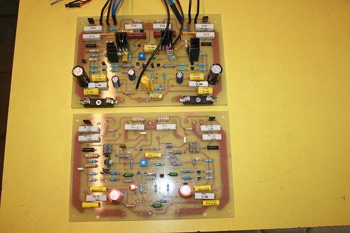
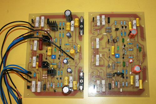
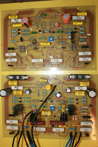
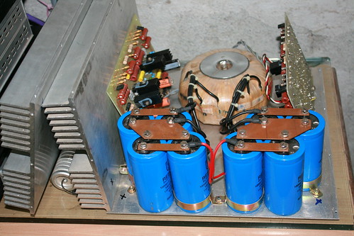
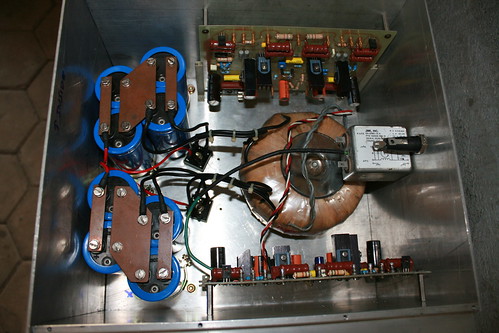
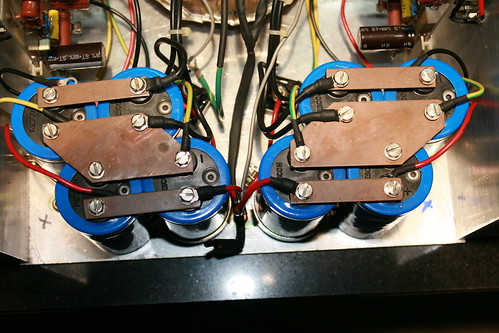
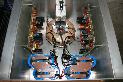
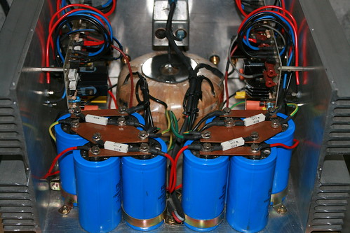
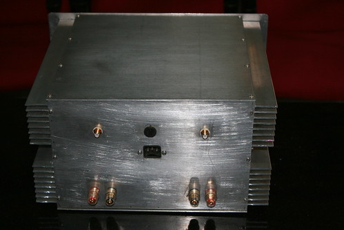
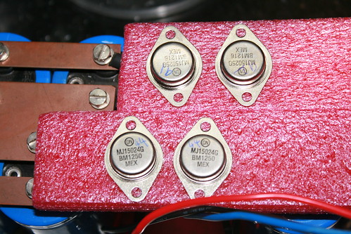
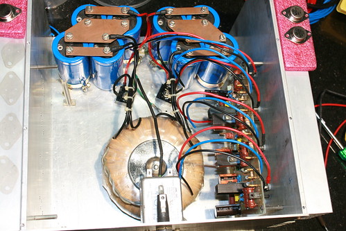
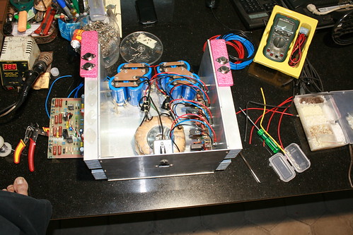
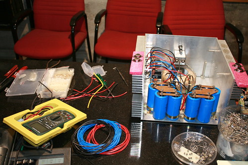
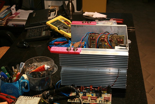
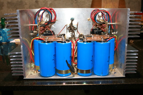
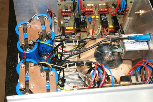
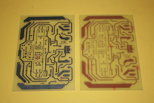
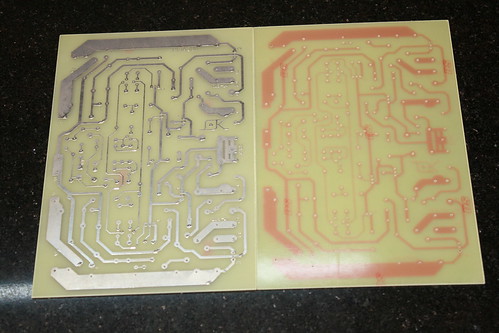
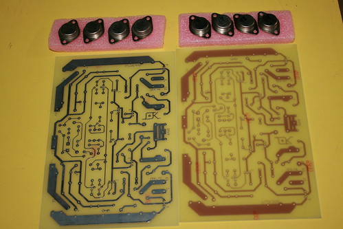
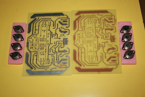
Building a 300 watt Hi-fi power amp, which we designed and prototyped few years ago.
Please follow the links for details.

310W Power Amplifier - diyAudio
310W Power Amplifier - Page 4 - diyAudio

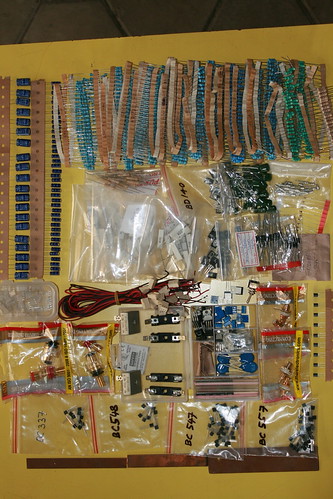
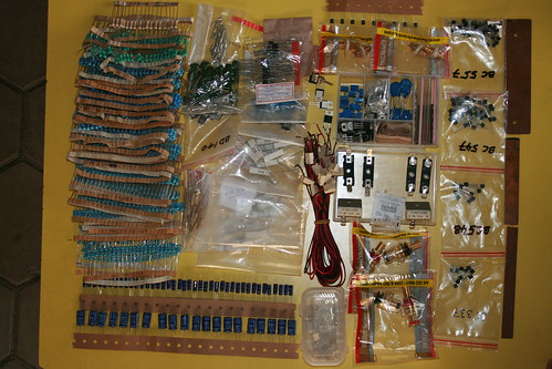
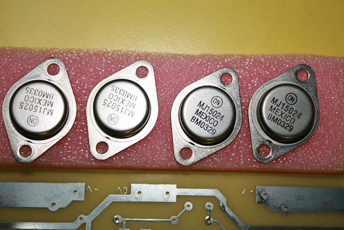
PCBs have been fabricated and gathering all components on hand.
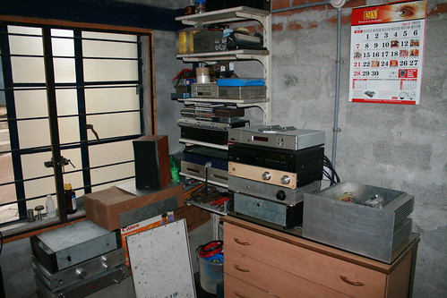
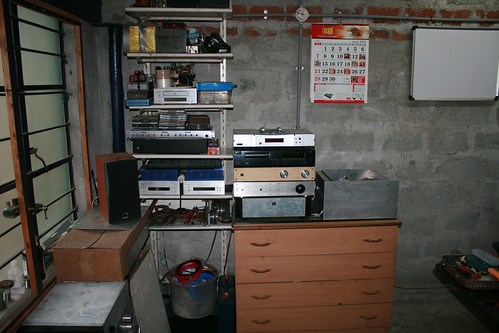
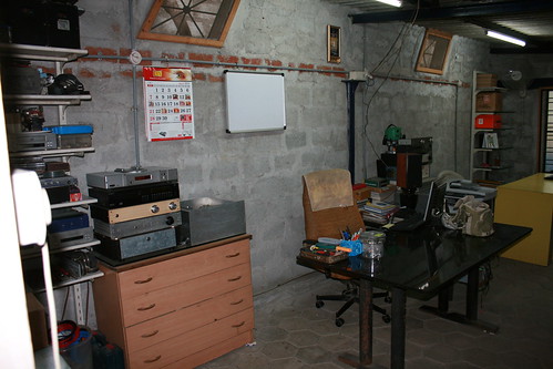
Few pictures of the same.


IMG_4459 by hydrovac, on Flickr


IMG_4458 by hydrovac, on Flickr


IMG_4461 by hydrovac, on Flickr


IMG_4462 by hydrovac, on Flickr


IMG_4570 by hydrovac, on Flickr


IMG_4575 by hydrovac, on Flickr


IMG_4465 by hydrovac, on Flickr


IMG_4464 by hydrovac, on Flickr
 
Nice to see a high power amp project on the forum.

Wow, i love those metal can trannies.......... :D
 
Last edited:
Great Build, hydrovac !

Any particular reason why you chose this design, which drives the output thru the collectors ? This implies gain by the output stage and therefore more feedback applied. These designs were popular in the era of high feedback (Which provide better thermal stability and lower steady state distortion, but today is looked on suspiciously for poorer sound ).

Love the attention you have paid to the Power Supply, including the Professional Grade Caps !

All the best.
 
Holes for output devices drilled on heat sinks using a TO3 jig. Input and speaker binding posts holes done and connectors mounted.


IMG_4448 by hydrovac, on Flickr


IMG_4366 by hydrovac, on Flickr


IMG_4556 by hydrovac, on Flickr


IMG_4481 by hydrovac, on Flickr

This is the den for our hobby & passion, and where all our classics come to life.


IMG_4399 by hydrovac, on Flickr


IMG_4398 by hydrovac, on Flickr


IMG_4397 by hydrovac, on Flickr


IMG_4396 by hydrovac, on Flickr


IMG_4315 by hydrovac, on Flickr


IMG_4314 by hydrovac, on Flickr


IMG_4313 by hydrovac, on Flickr


Power transistors mounting process and progress.


IMG_4420 by hydrovac, on Flickr


IMG_4412 by hydrovac, on Flickr


IMG_4409 by hydrovac, on Flickr


IMG_4416 by hydrovac, on Flickr


IMG_4414 by hydrovac, on Flickr


IMG_4412 by hydrovac, on Flickr


IMG_4449 by hydrovac, on Flickr


IMG_4442 by hydrovac, on Flickr
 
Im curious about the pieces attaching the lugs of the big caps.What is that material?how did you make it?
 
Holes for output devices drilled on heat sinks using a TO3 jig. Input and speaker binding posts holes done and connectors mounted.

Kudos - seriously elaborate metal work and assembly ! That's also a fairly serious amount of audio gear in the room. If you haven't already done so, you should hook up sometime with FMs Quad and Goldy Rathore in Hyd'bad.
 
Kudos - seriously elaborate metal work and assembly ! That's also a fairly serious amount of audio gear in the room. If you haven't already done so, you should hook up sometime with FMs Quad and Goldy Rathore in Hyd'bad.

Thanks linuxguru,

Some yesteryear projects and some branded gear living together.
Actually I sent a PM to quad sometime back but there was no response. So I left it there.

Cheers
 
Great Build, hydrovac !

Any particular reason why you chose this design, which drives the output thru the collectors ? This implies gain by the output stage and therefore more feedback applied. These designs were popular in the era of high feedback (Which provide better thermal stability and lower steady state distortion, but today is looked on suspiciously for poorer sound ).

Love the attention you have paid to the Power Supply, including the Professional Grade Caps !

All the best.

IndianEars,

Please go thru the links for answers which are self explanatory.

regards
Krishna
 
Hi Hydrovac,

I Did check Both the links, before posting here, asking you.

Maybe I am missing something ?

Can you please post here, the answer, or a link to the Specific page that provides an answer to my query ?

Sincere Thanks !
 
@FM Hydrovac
WOW! What kind of speakers do you intend to drive with this kind of power? Do share. This is going too be one interesting thread. All the very best for the build. Looking forward to the finished product eagerly.

Cheerio

Hi trittya,
I have a pair of Magnepan MG1.6QR.

Magnepan Magneplanar MG1.6/QR: Two-way, floorstanding dipole loudspeaker. Drive-units: 2" by 48" Quasi-Ribbon tweeter, 442-in.2 planar-magnetic bass driver. Crossover: 600Hz, low-pass 12dB/octave, high-pass 6dB/octave. Frequency response: 40Hz-22kHz, 3dB. Nominal impedance: 4 ohms (constant). Sensitivity: 86dB/2.8V/1m. Recommended power: 100W.

Primarily I am looking at improving sound quality, not necessarily increase in sound pressure level. So, what we are having here is, better dynamics and a small head room for those nasty (tasty!) transient peaks.

Regards
Krishna
 
Follow HiFiMART on Instagram for offers, deals and FREE giveaways!
Back
Top