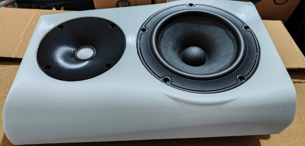
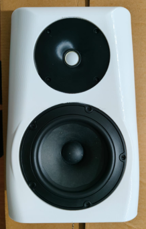
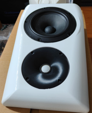
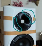
A 2way speaker with Peerless NE180-8 and SB26CDC/ADC

Before I finally go ahead with the build, I took some time to do detailed Akabak simulations of the waveguide in this final cabinet
For that, here is the process

1) Stripping down the cabinet to surfaces with only essential features
View attachment 93216

2) Integrating the waveguide with it
View attachment 93217

3) Meshing the whole thing
View attachment 93218

4) Doing sims in Akabak in half symmetry
View attachment 93219

Dome driver modeling of the SB26ADC/CDC using actual dimensions
View attachment 93220

5) Generating horzontal and vertical polars
View attachment 93221
View attachment 93222

6) Converting everything into a more easily visualizable format
View attachment 93223
View attachment 93224
View attachment 93225

We have good directivity control down to 1kHz.
The cabinet shape and depth help extend the usable directivity control of the waveguide from 2.6kHz (128mm diameter waveguide) down to 1 to 1.3 kHz. It is an octave more of directivity control for free.. :)
I am very happy with the way things are looking now.. :)
Appreciate your efforts and the science 🧪

For any diy person recommend to check ✅ audiofy.in and SB acoustics kits speakers 🔊 they are excellent quality drivers since the designers are ex scans speak
 
Here are some renders for extending the concept to a 3-way speaker with probably a Dayton RSS210HF sub
Total height = 620mm.
Total internal volume without braces and driver etc around 25litres
1759571323127.png
1759571359944.png


1759571426854.png
 
So here are the results with the normal cabinet (no teardrop shape) with the same depth, width (of the baffle region) and height. Basically everything else remains the same as before

1759673199910.png


1759673262249.png


1759673271993.png


1759673284731.png


Here is a comparison of the horizontal polars between the teardrop cabinet version and the above cabinet

Teardrop cabinet
1759673384218.png


Rectangular cabinet
1759673339850.png


The most obvious difference between the two is the null around 110 degrees and the adjacent peak around 800Hz. In the teardrop version, the peak-dip combination is smoother.. So cabinet shape does have an impact..
Then there is ever so slight widening of radiation around 9kHz. I think this is because I reduced the dome-radiating area in the simulation to dome + half surround instead of dome+full surround in the teardrop cabinet simulation from earlier. So overall slightly less radiating area leading to wider pattern. But in the real world, I dont think it is going to be of any consequence and is situation/simulation specific
1759673718040.png


Another thing to note is that the above polars are generated by the tweeter alone. That is an omnidirectional "ish" source (this tweeter at 800Hz) is illuminating the whole cabinet to cause this kind of peak-dip combo near 800Hz.
In real world, this region will be handled by a 6.5-inch midbass driver, which will probably illuminate slightly less of the cabinet at 800Hz, I guess, because of it becoming more directional than the tweeter in this range.

However, it is still a mild compromise. I might never be able to hear the difference in real world I guess, but now that I have seen the difference, I dont feel it easy to neglect it.. :)
 
Now we starting bringing in the woofer and study its impact.
The BEM sims below were donewith the cone woofer with the rectangular cabinet.
The cone is 131mm in diameter, the same as that of the NE180.
I might have given unnecessarily high mesh resolution to the waveguide area in this one.

1759800059875.png


1759800070699.png


1759800090249.png


1759800100394.png


Interestingly, the near 800Hz peak-dip combo is still there in the horizontal polars..
 
For reference, the woofer performance in the shaped cabinet looks like this
1759847707015.png


1759847766500.png


1759847785367.png


1759847803200.png


The near 800Hz peak-dip combo due to cabinet back edge diffraction is much better and smoother here in the horizontal polars
 
With the frequency response curves from the simulation, at least this kind of result looks possible.
In this simulation, I have taken a 175mm vertical distance between the tweeter in the waveguide and the midwoofer
1759851744639.png
 
Can you check whether use of asymmetric crossover improves the narrowing near 2K? Earl Geddes says his speakers have a vertical lobe directed at the floor to minimize its effect, that's quite smart, can it be replicated?
 
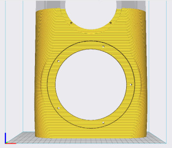
I got the waveguide printed in PETG for testing fit and maybe some experimentation as well.
1759552749590.png


1759552771150.png


It has some imperfections in printing. The indicated part below shows some small issues near the surround.
I hope some measurements will tell if they have any impact
1759552865119.png


I printed the baffle as well and the drivers fit nicely. It feels very solid.
This is for initial measurements. Final cabinet will be done in MDF/birch ply after I finalise the speaker design to make it a 3-way, 2-way or a 3-way with cardioid midrange. Right now, I am very biased towards a cardioid mid arrangement & subwoofer at the back arrangement, like the Dutch & Dutch 8C/6C
1760186493927.png
1760186500564.png1760186506807.png
 
Vineeth, how much infill do you use?
And with 3D printing 3D honeycomb like structure baffles can be printed that are super stiff and very light, it increases stiffness taking resonance higher, the honeycomb can be filled with silicon (not normal silicon glue, the variety that stays elastic) to add sufficient damping. I believe it will be super dead sonically.
I hope you try something like that in your next build, printing time would be very less due to less use of actual PETG material in honeycomb structure, only screw places need be be totally solid, rest all honeycomb. I remember some waveguides had ribs on the walls (outside) that were filled with some damping material, my inspiration comes from it.
 
@diyaudio:
I have had similar ideas about 3D printing this baffle.. :)
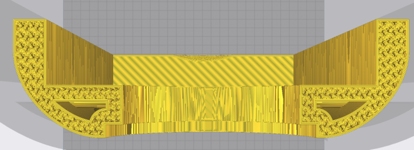
So this print is done with just 15 per cent infill, wall count=4 and with gyroid infill. It also has hollow spaces inside, throughout, to be filled with some damping material.
However, even now, the printed baffle is incredibly stiff and feels like a concrete slab that is just lighter in weight.. :)
The idea has been to fill it with some sort of damping material. And I am pretty sure it will become even more inert.
But I am not even sure that is necessary at the moment. But will give a try.
Here is a cutaway showing the details of the inside of the baffle while 3D printing

Top view
1760264892293.png
Front view
1760264945854.png
 
I just couldn't wait without measuring.. :D
So, I created a "box" for the baffle using a cardboard box and took some quick and dirty measurements of the tweeter from 0 degrees to 90 degrees.
The measurements are not perfect and has a low level relection coming in around 3s.
But I still windowed at 4.1ms.
1760287418528.png


Tweeter in waveguide: Measurements
1760287450010.png


The axial response has a dip at 10kHz
1760287533217.png


However, if I design a crossover using 10 degrees off-axis response, here is how simple it looks for a 1600Hz LR4
1760287614374.png


1760287604352.png


1760287634320.png


1760287646069.png


Here is a comparison between the BEM sims I did for the tweeter in the waveguide in a rectangular box

Comparison between BEM simulation and measurements
1760288289456.png


The dotted line is the BEM sim SP DI curve while the solid red line is the measured SP DI curve with 0 to 90 degrees measurements only..
I couldn't expect a better match than this I guess, atleast upto 10kHz
Why do we need Klippel nearfield scanner when we can do things like this in just software.. ;)

Also, overall, it looks surprisingly ok, I think.. :)
Do I need to do something about that 0 degrees on axis dip at 10kHz is the question that I am thinking about..
I have recently seen a dip like this in @stv's tweeter measurements, subsequent discussion, and a potential solution for that.. I am still thinking if it is worth redesigning the waveguide..

I tried moving around the tweeter while playing the sinesweep, and I couldn't hear anything abnormal on and off axis, though..
It is a very clean-sounding tweeter in general..
 
It definitely looks like the 10kHz dip is due to the uenevenness in the throat diameter.
Warping of the print around the throat area seems to have caused the issue.
There is approx. slightly >1mm gap from the diaphragm edge to the waveguide wall at the portion where the gap is maximum.
1760372120779.png


So I tried to fill that area slightly with some modeling clay and below is the result. Basically no w the dip is 2-3dB less
1760372872831.png


1760372044692.png


And while at it, I took the full 180-degree polars (again, quick and dirty)
1760372788198.png


1760372779353.png


1760372802145.png


So it looks like I might have to get the waveguide printed again properly this time if I am to get that gold star.. :D
 
Order your Rega Turntables & Amplifiers from HiFiMART.com - India's reputed online dealer.
Back
Top