A 3-way active crossover design study

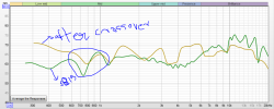
More Updated: Measurement session - part 2

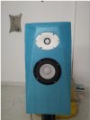
I have finally completed a prototype box with the baffle attached to it. The box size for the mid is currently about 10 L in volume. Using this, I have tried to do full 0 to 90 degree measurements in the horizontal plane on for both the mid driver SB15CAC30-8 and the tweeter SB26CDC004 i 4 inch waveguide. Looks like they came out well. :)
The tweeter in the waveguide looks too good. Now it is time to start thinking about building the actual enclosure.
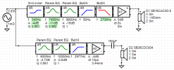
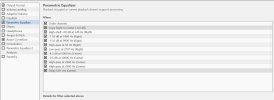
In the meanwhile, I will use these measurements and VituixCAD to design a prototype crossover.

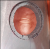
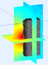
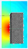
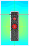
Pic-1 shows drivers on baffle
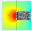
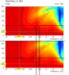
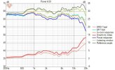
Pic-2 is the nearfield measurement of the mid
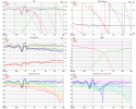
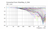
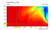
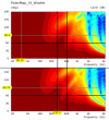
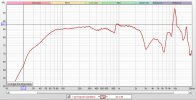
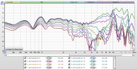
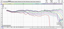
Pic-3 is the gated far field measurement set for mid (gate = 4ms)
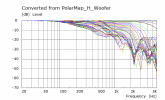
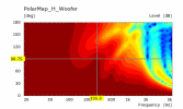
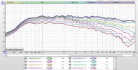
Pic-4 is the gate far field measurement data for tweeter (gate = 4ms)

Thanks
Vineeth
 

Attachments

  • baffle.JPG
    baffle.JPG
    44.8 KB · Views: 29
  • nearfied_mid.JPG
    nearfied_mid.JPG
    167.5 KB · Views: 28
  • SB15CAC8_polar.JPG
    SB15CAC8_polar.JPG
    209.5 KB · Views: 20
  • SB26CDC004_polar.JPG
    SB26CDC004_polar.JPG
    188.7 KB · Views: 27
Updates: Cabinet construction

I have started playing around with fusion 360 to study and create a final cabinet design and generate details about estimated MDF/PLY & other materials that are needed. As per advice that I got over at diyaudio from FM Augerpro, I want to do a constrained layer damping (CLD)-based cabinet and bracing but dont know about its feasibility at the moment and hence trying to get more details.
In the meanwhile , here are some pics of the final intended cabinet shape (without any bracing added) :)
 

Attachments

  • 3way_speaker_FRONT.jpg
    3way_speaker_FRONT.jpg
    16.2 KB · Views: 26
  • 3way_speaker_v8.jpg
    3way_speaker_v8.jpg
    20.9 KB · Views: 27
I don't know if anyone here in India had tried this CLD technique. Secondly I think one can get the best results only if the sheets are first glued with each other and then cutting is Done, & this job can be only done if any one has an access to such a huge hydraulic press. One can find such Press at flush door manufacturing unit. So if you know any such manufacturer then you are lucky.
 
Yes, the layers will need to be first glued first and then cut, but it's not necessary that 8' x 4' sheets be glued and pressed with a large press. Smaller roughly cut pieces can be glued together and bonded without a press. We have enough junk lying around to place over layers to press them down. Then cut to size. Very doable!
 
Yes, the layers will need to be first glued first and then cut, but it's not necessary that 8' x 4' sheets be glued and pressed with a large press. Smaller roughly cut pieces can be glued together and bonded without a press. We have enough junk lying around to place over layers to press them down. Then cut to size. Very doable!
In CLD the glue should have even thickness throught the contact area, or else it will not do the work as it has to do, this can be only possible when done on a press which has an area equal to the area of your baffle, so that one can apply pressure evenly throught the contact area. If you press it with uneven pressure then i dont think it will work as intended, the glue will have unevenness throught the contact area, may be at some points both the surface will come in direct contact with each other (I hope you get what I mean to say).
 
Hi..
Thanks for the suggestions.
Augerpro has 3D printable trowel for uniform glue application here:

Interesting discussions about this project can be found here also:
 
In CLD the glue should have even thickness throught the contact area, or else it will not do the work as it has to do, this can be only possible when done on a press which has an area equal to the area of your baffle, so that one can apply pressure evenly throught the contact area. If you press it with uneven pressure then i dont think it will work as intended, the glue will have unevenness throught the contact area, may be at some points both the surface will come in direct contact with each other (I hope you get what I mean to say).
True if the specialized glue is the damping layer. What I was referring to (and which I didn't specify) was the damping layer being other than glue and glue used only to bond the damping layer to the outer layers. Even if the glue were to be used as the damping layer and there were to be uneven pressure on the whole surface area, I don't think we should go OCD on it. It'll work!
 
To have some more confidence with measurements and to have some sort of a reference, I measured my Q Acoustics 2020i speakers today (Quasi anechoic gated at 3.7ms + nearfield wit baffle step correction applied and merged).
Attached pics show how the far field response looks like and the power response directivity etc got from VituixCAD.
 

Attachments

  • VituixCAD Power_DI_QA_202i.jpg
    VituixCAD Power_DI_QA_202i.jpg
    44.4 KB · Views: 16
  • QA2020i_directvity.JPG
    QA2020i_directvity.JPG
    179.9 KB · Views: 13
Miscellaneous updates on this project
I tried to implement the DSP crossover in JRIVER software and used my 6 channel ESI U86XT soundcard for implementing it. I connected it to the current foam box where the drivers are mounted on and made it play some songs. I have attached screen shots of the crossover I designed the crossover in vituixCAD and did its implementation of it in JRIVER. The measurements used for designing the crossover are horizontal polar only ones I had taken and posted about the mid and tweeter in a previous post. I attached pics of above details below. One thing I understood from this exercise is it is really a hassle for a beginner with software dsp crossover compared to the plug and play approach of MiniDSP etc. But eventually I made it work :D
I also think I have some clue about the weirdness around 1 kHz in my mid driver frequency response measurement plots in above posts. I think I got some clues from measurements and graphs here which FM Juhazi had given me on diyaudio chamfering driver holes
It could be due to the lack of a sufficiently deep chamfer around the back of the mid on my foam baffle. The baffle depth is about 55mm. I attached a pic below about this. I now made a generous chamfer at the back of the mid now and tried to take a basic on axis frequency response measurement of the full prototype speaker (except the woofer) as described above with the DSP crossover in place. The chamfer issue seems to have reduced but I see all sorts of weirdness in the response especially at higher frequencies... :D I have attached pics of it below.

I just didn't bother debugging the crossover implementation issue since the prototype box itself could be faulty and the crossover implementation could also be the issue with the measurements I took. I have some clues about what went wrong there too.. :D Somehow I heard it sing well though :p even with the weirdness in measurements. However one thing I noticed straight away is a kind of disconnected sound in some songs when I was very close to the speaker (really close, like 30cm away, which will probably not happen in a real listening session since I am not planning to use this for nearfield). About 2m+ away from the speaker, it was sounding better to me. Again, this could all be due to the crossover implementation. Could be due to the vertical spacing between mid and tweeter also, I think.

I think this current prototype box has reached the end of its life. From now on I will probably work only on a real final box for measurements. Seems like I really have a long long way to go and need to learn a lot more :D
 

Attachments

  • 3wayactive_with_hor_polar_meas XO-schema-1.png
    3wayactive_with_hor_polar_meas XO-schema-1.png
    17.2 KB · Views: 18
  • 3wayactive_with_hor_polar_meas Six-pack.png
    3wayactive_with_hor_polar_meas Six-pack.png
    163.3 KB · Views: 16
  • DSP_crossover_details.JPG
    DSP_crossover_details.JPG
    111.8 KB · Views: 18
  • mid_inner_chamfer.PNG
    mid_inner_chamfer.PNG
    531.5 KB · Views: 17
  • REW_measurements.PNG
    REW_measurements.PNG
    163.2 KB · Views: 18
Other related developments and some rambling

Many forum members on diyaudio forum inlcuding Augerpro, Fluid, hifijim, Juhazi, tmuikku, and others have been helping me learn and constantly improve my knowledge about several design aspects through constantly asking questions, giving suggestions, and even going out of their way to really take the learning aspects involved this project to higher levels. One such development in this regard is trying to do simulations about my baffle's and cabinet's impact on sound radiation that FM fluid is doing with FM Augerpro's support. He has even been trying to help me learn Fusion 360. I can't thank them enough for doing all this. Here is a snapshot of the development of the 3D model of a simplified version of my cabinet for simulations.
3 way complete.png

Hopefully, some real learning will come out of this and help me with this project.:)

That said, I am really thankful to FMs tcpip, Keith Correa, and Sadik and others for helping me out by giving very useful suggestions in some aspects earlier. FM tcpip's posts in this forum and his website are what inspired me to take up this hobby of learning about making speakers a few years back. And I have been learning more about it everyday. Everyday I become more fascinated by it than ever. It has also really helped me with taking my understanding of my area of specialization (signal processing applied to wireless communication devices) to much higher levels.

Once someone asked on this forum, what I myself has contributed to this forum that makes me eligible to ask questions. Well, I believe now I have reached the limits of my knowledge regarding sharing what I know. Anyone interested can read my posts earlier on in this forum and see if you find something useful for you. Of late I have been seeing some negative vibes, which I don't want to have anything more to do with. I believe knowledge sharing will happen and be useful only if there is a fertile ground for it and there are people interested in it.

Anyway, enough of the rambling. This will hopefully be amongst my last posts here. Anyone interested in this project and wanting to more about what happens in future, please visit
:)

Thanks
Vineeth
 
Everyday I become more fascinated by it than ever. It has also really helped me with taking my understanding of my area of specialization (signal processing applied to wireless communication devices) to much higher levels.
You're doomed! :p
Once someone asked on this forum, what I myself has contributed to this forum that makes me eligible to ask questions.
I wasn't aware that contributing to the forum was a pre requisite to asking questions. It's insane! Really!
This will hopefully be amongst my last posts here.
Don't do this. Rethink! Don't let them win. :mad:
 
I am back :D hopefully with some useful info.. :p
I am sharing some results I got to see from wave front simulations (which tell us things about the impact of cabinet/baffle shape in the 3 way speaker design that I have been talking in this thread) that FM fluid on diyaudio did. These are simulations on a 28cm wide, 40cm deep, 105 cm high speaker cabinet with 30 degree chamfers on the baffle.
Attached pics shows these results:
Brief explanation about the plots:
In the first 4 plots, it shows the impact of cabinet shape when a 400Hz signal is trying to radiate out of the woofer.
In general, we are looking at the shape of the directivity and the relative intensity of the sound shown by colour from hot to cold, red to blue, high to low.
There are three planes drawn one through the woofer which can be seen from the top down and two others through the centre splitting the speaker in half and a plane through the center of the cabinet going up.
Where the shape expands out shows the shape of the lobe and how even that is. The nulls forming on the back corners of the cabinet are where there is negative interaction which is shaping the directivity at far off axis angles.

Pics 5 & 6 shows the cabinet impact on radiation over the entire frequency range on the the mid and woofer radiation up to 5kHz. These are captured by the normalized polar plots when the angle changes from 0 degree to 180 degree in the far field along the direction shown by the arc around the tweeter at the height of the tweeter. Last two Pics show the same information using line charts.
 

Attachments

  • 400Hz400mmDiag.png
    400Hz400mmDiag.png
    97.8 KB · Views: 8
  • 400mm Deep H Polar Mid Curves.png
    400mm Deep H Polar Mid Curves.png
    21.7 KB · Views: 7
  • 400mm Deep H Polar Curves Woofer.png
    400mm Deep H Polar Curves Woofer.png
    22.5 KB · Views: 6
  • 400mm Deep H Polar Woofer.png
    400mm Deep H Polar Woofer.png
    36.8 KB · Views: 5
  • 400mm Deep H Polar Mid.png
    400mm Deep H Polar Mid.png
    30.1 KB · Views: 4
  • 400Hz400mmTD.png
    400Hz400mmTD.png
    37.8 KB · Views: 4
  • 400Hz400mmSide.png
    400Hz400mmSide.png
    95 KB · Views: 5
  • 400Hz400mmFront.png
    400Hz400mmFront.png
    87.5 KB · Views: 5
Last edited:
So what are we observing above: My Interpretations about impact of cabinet depth on radiation characteristics

It looks like diffraction is happening at low frequencies. As we can see trends like peaks changing to nulls when the depth is doubled at a given frequency (for example around 350 Hz), it looks like a comb filtering is happening, with the varying depth, in turn, varying the delay that forms a part of the comb filter.
I am thinking it is the edges of the box at the back side and the top that is causing the main issues (abrupt change in acoustic impedance as the wave transitions suddenly from material of the box into free space, which is causing secondary waves to propagate from there and interfere with the waves produced by the driver at the off axis angles we are seeing main issues. There is definitely a vertical component involved as well, whose influence could be more visible in a vertical polar, I think.

I have attached comparison plots of the midrange (Pic-1) and woofer (Pic-2) with this post. Top figure in each case is the 200mm cabinet depth and bottom one corresponds to the 400mm cabinet depth. The effect of a peak changing into a null-type of phenomenon is clearly visible in the polars of the mid driver. I think, since, in the mid driver's case, the effect of horizontal plane might be more significantly seen in these horizontal polars (as it is closer vertically to our observation point), the change in depth and the resulting discontinuity at the edge (at the back) is causing the major issue below the 500Hz range.

Another thing I am seeing is as the depth increases, the location of the main peaks are moving lower in frequency, which could be better for the mid, if we could smooth out the secondary peaks that come higher in frequency. It could also help the woofer somewhat, if we can smoothen the main peak.

Based on all this, I am thinking that instead of the really boxy shape I have, if I had smoother transitions/round overs/chamfers at all edges (back, top, everywhere possible), the difference in amplitudes of these peaks and dips might smooth out (I am thinking that is why revel M16 type or more "ellipsoidal" type enclosures would be better instead of the rectangular box). I don't know if the edge treatment around the baffle would help with the woofer radiation at this lower in frequency, but it is definitely good to have smoother transitions everywhere, I think..
biggrin.gif


I am attaching some pics of the kind of cabinet shapes that might help us smooth out the peaks and dips. Even if all of these shapes may not be DIYable for me, at least if the hypothesis is correct, we might be be able to get better graphs with these kind of shapes/simplified versions of them I think..
biggrin.gif
biggrin.gif
 

Attachments

  • Mid_polar_comparison_20cm_vs_40cm_depth.png
    Mid_polar_comparison_20cm_vs_40cm_depth.png
    143 KB · Views: 6
  • Woofer_polar_comparison_20cm_vs_40cm_depth.png
    Woofer_polar_comparison_20cm_vs_40cm_depth.png
    164.5 KB · Views: 9
  • rockport_atria_2.PNG
    rockport_atria_2.PNG
    186 KB · Views: 8
  • TAD_evolution_one.PNG
    TAD_evolution_one.PNG
    251.8 KB · Views: 9
  • TAD_reference1.PNG
    TAD_reference1.PNG
    780.5 KB · Views: 11
Last edited:
So what does it all mean if the above hypothesis are correct

Anyway, these are all studies about cabinet impact on low frequency radiation. At higher frequencies around tweeter range, we can do other things also to smoothen out radiation.
I have been preaching about impact of cabinet shapes and smoothness for a while, and people have mostly only hated me for it. :D:p
If the interpretations are true, we need smooth shapes overall (whereever possible), minimize abrupt changes in acoustic impedance. Maybe diffraction at far off-axis angles may have minor impact. But it is still an impact which depends on our listening position and room in which the speakers are placed. All these are objective, off course. But we are trying to do our best in acoustic design of the cabinet. At least we would have done our part. Then let the room take over and play spoilsport :D Then we can think about room treatment and all sorts of things to tame the room.
Subjectively, what does it all account to. Honestly, I don't know yet. Hopefully, in smoother sound balance.
We may not get the "diffraction-bite" which some people may like and some others like me don't. :D

Please chime in if you have other interpretations from above graphs. Mine could be wrong also:D

Note: I have not heard the revel M16 or any of the speakers whose pictures I posted above. So I dont know what they all sound like or if they are better. I am justing talking about shapes and geometry here. :) Much more needed (even in objective terms, let alone subjective) to "good sound", whatever that is to different people
 
Last edited:
@Vineethkumar01 Why not completely isolate the mid drivers in their own enclosure within the main enclosure. You can also make the enclosure dimension uneven to mitigate standing waves and also use enough damping to absorb the internal waves.

To reduce cabinet resonance, another method though not commonly employed, is to not screw the drivers to the enclosure but kinda use the magnets to lock them to the cabinet from inside and use some foam or rubber to seal the space between baffle and enclosure on the front (this technique is called something which I don't recall now). I think @yogibear has employed this method to good effect.

Another method to reduce cabinet resonance is to use addition panel of wood to the surface on which which the driver is mounted. I have used this method effectively in my speakers.
 
Thank you @Kannan and @yogibear for your suggestions. Yes mid drivers will be isolated in their own sealed enclosures. I will study more about other suggested techniques too. :)
I think what you are referring to is cabinet resonances. What I was trying to show with those plots are the effects of cabinet diffraction. Normally diffraction effects are studied only at the higher frequency range, specifically around the tweeter radiation range. We do things like roundovers and chamfers and driver offsets, and waveguiding etc to tackle that. Here I am trying to show how the outside edges of the cabinet affect radiation and lower frequency ranges. Or how the cabinet shape (the outside part) interacts with cabinet radiation. Turns out as per the graphs that the location where the driver is mounted, the cabinet width and depth will affect the directivity of the system. frequency response measured at angles around the speaker. We want this to be as smoothly varying as possible before it interacts with other boundaries of the environment it is placed in. :)

So, in summary, the above results are about how the outside of the enclosure looks (whether it has sharp edges or rounded) and its relatively less studied impacts on lower midrange
 
Back
Top