You are using an out of date browser. It may not display this or other websites correctly.
You should upgrade or use an alternative browser.
You should upgrade or use an alternative browser.
A 3-way active crossover design study
- Thread starter Vineethkumar01
- Start date
Vineethkumar01
Well-Known Member
Yes,Series 800 of B&W speakers have similar shapes for mid & highs
In fact the B&W speaker enclosures are one of the motivations behind these kind of enclosure shapes.
1) The other considerations are Olson's diffraction studies from long back showing sphere having amongst the least diffraction..
2) Recent 3D printed (in SLS nylon process I think) enclosure-based transmission line speakers like these:
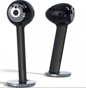

HYLIXA • Node Audio Research
Lose yourself in music. Experience a lifelike reproduction of sound. Liberated from conventional manufacturing, HYLIXA’s innovation and strength are only possible by exploiting techniques new to the audio industry.
3) Recent studies on diyaudio which show that the enclosure itself acts as a waveguide for the speaker (I am not worried about high frequency edge diffraction as that will be taken care of by the mid-driver which acts as the waveguide for tweeter). My interest is in lower frequency diffraction control for the mid driver and seeing how these kind of low diffraction enclosures extend directivity control right down into the midrange frequencies..
Vineethkumar01
Well-Known Member
So from looking at the driver I will have as shown below, its frame itself has a slight curvature. 
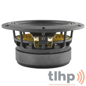
I am going to blend that angle into the enclosure shape and modify the enclosure based on that so that the curve that starts at the driver frame continues and I can use the whole enclosure to guide the sound waves..
Unfortunately I have to wait for 2-3 weeks more to get the drivers.. Then the fun begins..
Music has No Religion, No Language and No Boundaries............PS: The language used in the lyrics of the video (Malayalam) might seem like gibberish but it is my native language..
Thanks
Vineeth
keith_correa
Well-Known Member
My thoughts, exactly! And, also, I would have a curve radius of at least an inch and a half for maximum effect.<snip>I am going to blend that angle into the enclosure shape and modify the enclosure based on that so that the curve that starts at the driver frame continues <snip>
Vineethkumar01
Well-Known Member
Okay so while I wait for my coaxes to arrive, I am thinking and working on my System-3 
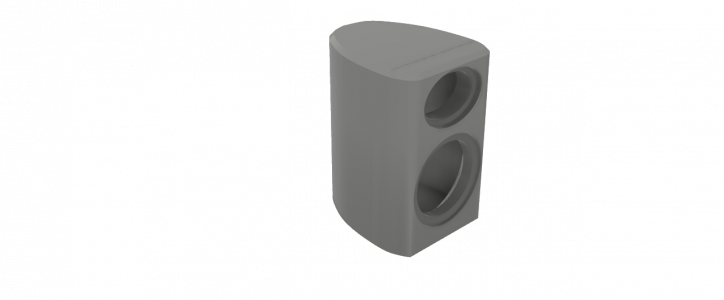
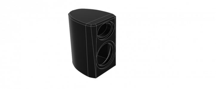
This is a traditional 2 way speaker with a shaped baffle and waveguided tweeter. I want the cabinet shape to look like below:
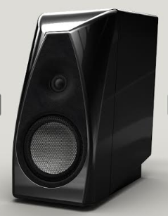
I don't mind the color of the drivers and the waveguide...
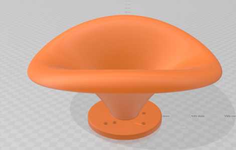
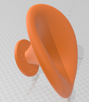
What I want is that overall similar cabinet shape but with my elliptical waveguides designed by augerpro.
Again, the bass and upto 350ish Hz will be handled by my Satori woofers in a 3 way configuration.
So these are the drivers I have available:
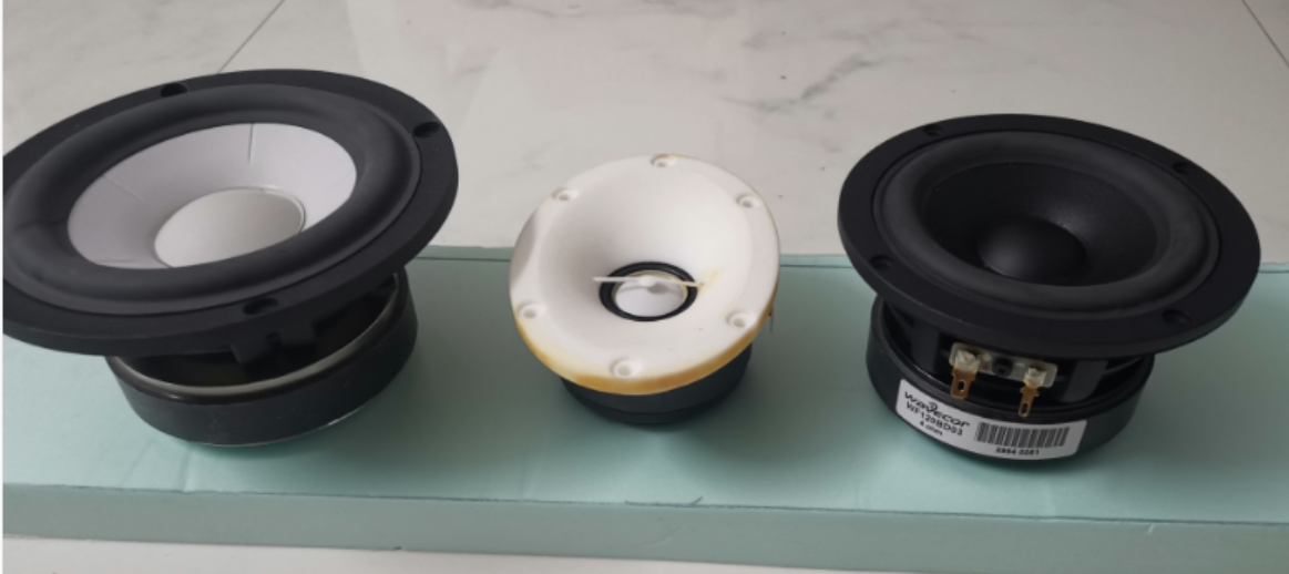
On the Left is SB15CAC, Middle tweeter is SB26CDC to be mounted on elliptical waveguide (printed in SLS nylon in the past. The color has faded and sort of yellowed), and on the right is Wavecor WF120BD03.
I am almost torn between the two mid drivers thinking about which one to use.
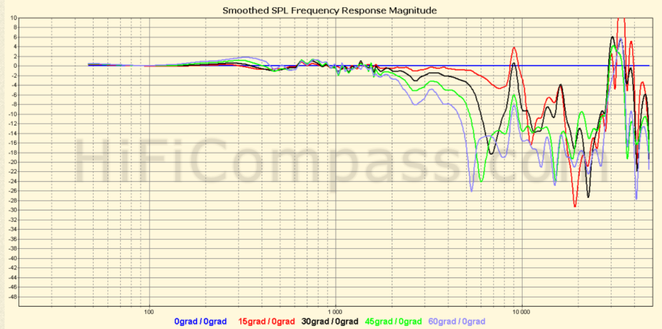
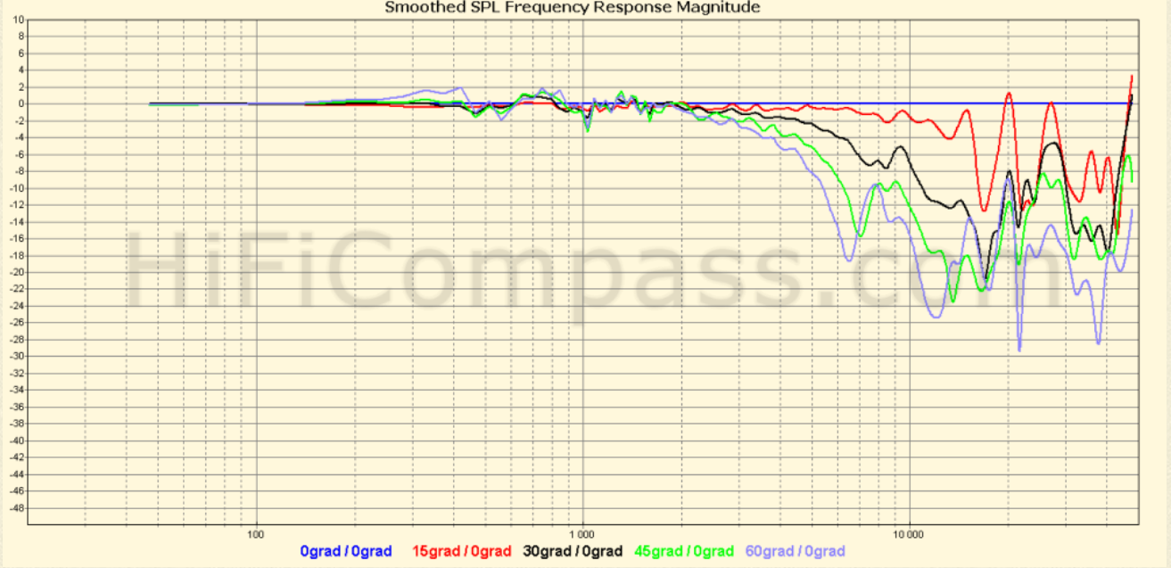
Here is how their normalized polars shown on hificompass website looks like:
Polars for SB15NBAC:
Polars for Wavecor WF120BD03:
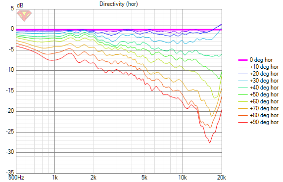
Here is the(upto 90degree measurements) I captured with the tweeter waveguide combination (on my foam box chamfered baffle box), again with a 150uF capacitor in series with driver (this was captured at a time when I was learning to take measurements, so could be wrong also to some extent.. ):
):
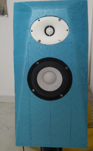
Foam box pic:
Waveguided tweeter measurements
I like the looks of polars better for the wavecor (it is also a really really cute little driver and looks very well built) but power handling and distortion may also need to be considered before I pair up the drivers. Here is where I am a little confused.
Which one should I go for driver choice-wise?
Due to the constraints in the place and situation I live in, I cant do much woodworking myself. I am really tired asking around for help from people here in India regarding building the cabinets I design. Literally heart broken..
When I say I want 1inch roundover, they say it doesn't matter much. we will do a 1/4th inch roundover. When I say I want a chamfer, they say, it wont affect and we have really nice speakers with no roundover/chamfer. Those who know proper woodworking here don't care about speaker building projects. CNC guys are the worst.. They just don't care about the whole thing. Not even interesting in cutting an MDF sheet into rectangular pieces.
Due to all this, I am going to keep this two way build smaller (but not to the extent of introducing a lot of compromises acoustically).
So if everything else fails I am going to 3D print the baffles myself. And try to assemble a small enclosure to put it along with the drivers..
  I have few pieces of baltic birch plywood 3mm thick left over at home. I will use that to make a small box with plywood on either sides of xps foam and make a CLD box for the baffle
Thanks
Vineeth
This is a traditional 2 way speaker with a shaped baffle and waveguided tweeter. I want the cabinet shape to look like below:
I don't mind the color of the drivers and the waveguide...
What I want is that overall similar cabinet shape but with my elliptical waveguides designed by augerpro.
Again, the bass and upto 350ish Hz will be handled by my Satori woofers in a 3 way configuration.
So these are the drivers I have available:
On the Left is SB15CAC, Middle tweeter is SB26CDC to be mounted on elliptical waveguide (printed in SLS nylon in the past. The color has faded and sort of yellowed), and on the right is Wavecor WF120BD03.
I am almost torn between the two mid drivers thinking about which one to use.
Here is how their normalized polars shown on hificompass website looks like:
Polars for SB15NBAC:
Polars for Wavecor WF120BD03:
Here is the(upto 90degree measurements) I captured with the tweeter waveguide combination (on my foam box chamfered baffle box), again with a 150uF capacitor in series with driver (this was captured at a time when I was learning to take measurements, so could be wrong also to some extent..
Foam box pic:

Waveguided tweeter measurements
I like the looks of polars better for the wavecor (it is also a really really cute little driver and looks very well built) but power handling and distortion may also need to be considered before I pair up the drivers. Here is where I am a little confused.
Which one should I go for driver choice-wise?
Due to the constraints in the place and situation I live in, I cant do much woodworking myself. I am really tired asking around for help from people here in India regarding building the cabinets I design. Literally heart broken..
When I say I want 1inch roundover, they say it doesn't matter much. we will do a 1/4th inch roundover. When I say I want a chamfer, they say, it wont affect and we have really nice speakers with no roundover/chamfer. Those who know proper woodworking here don't care about speaker building projects. CNC guys are the worst..
Due to all this, I am going to keep this two way build smaller (but not to the extent of introducing a lot of compromises acoustically).
So if everything else fails I am going to 3D print the baffles myself.
Thanks
Vineeth
Vineethkumar01
Well-Known Member
Vineethkumar01
Well-Known Member
Vineethkumar01
Well-Known Member
So I 3D printed my first waveguide/horn. 
It is the ATH generated ST260 KVAR with 1inch throat. This was a real learning experience in 3D printing even though i would have probably wasted about 250+ gm of PLA+ filament material.
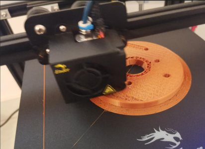
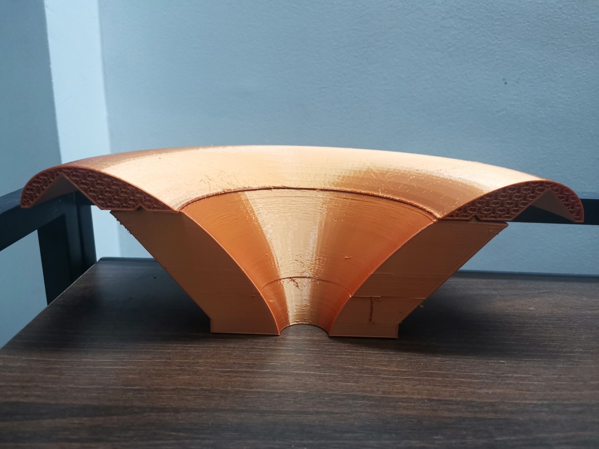
I started with the regular ST260. Fluid had given me the STL files that he had designed. I tried to print it but my printer screwed it up due to the longer print times involved due to power failure related issues in my area, support failures during printing, wrong infill settings, etc. Here is what I salvaged from the whole set of disasters. Probably a close to half of the waveguide. If this had completed properly, I would have had a much better looking and feeling waveguide than what i currently have.
Dejected by the failures, I first bought a UPS for my 3D printer, then to learn this entire thing about how to assemble a waveguide printed in parts, I decided to print the KVAR version of ST260 in 5 parts. 4 petals + 1 throat piece.
Surprisingly, I was able to print the parts and assemble it together. Again each part was a learning experience in 3D printing. Hemce the petal looks and finishing varies across the different parts..
Here are some pics of what i currently have.
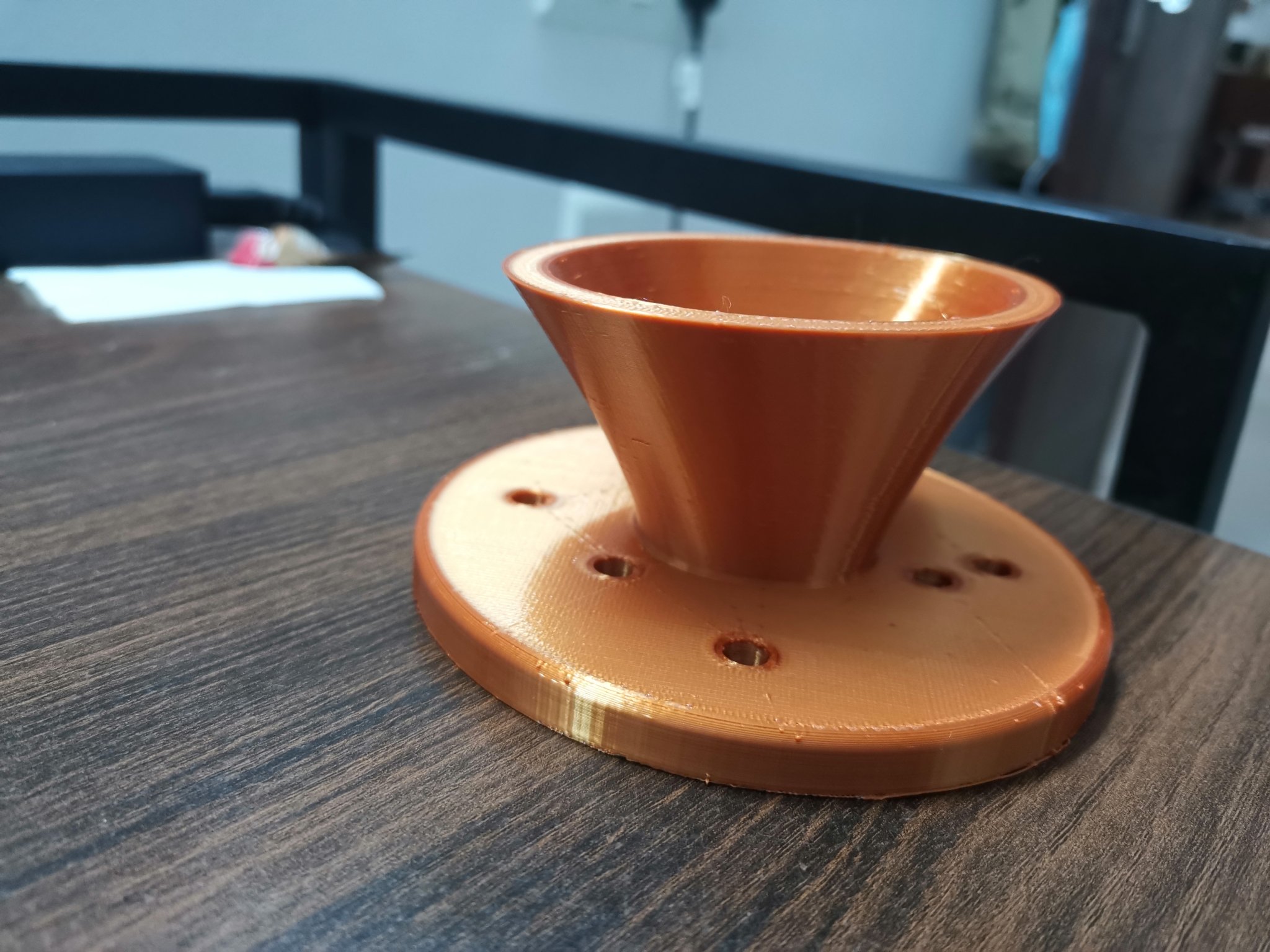
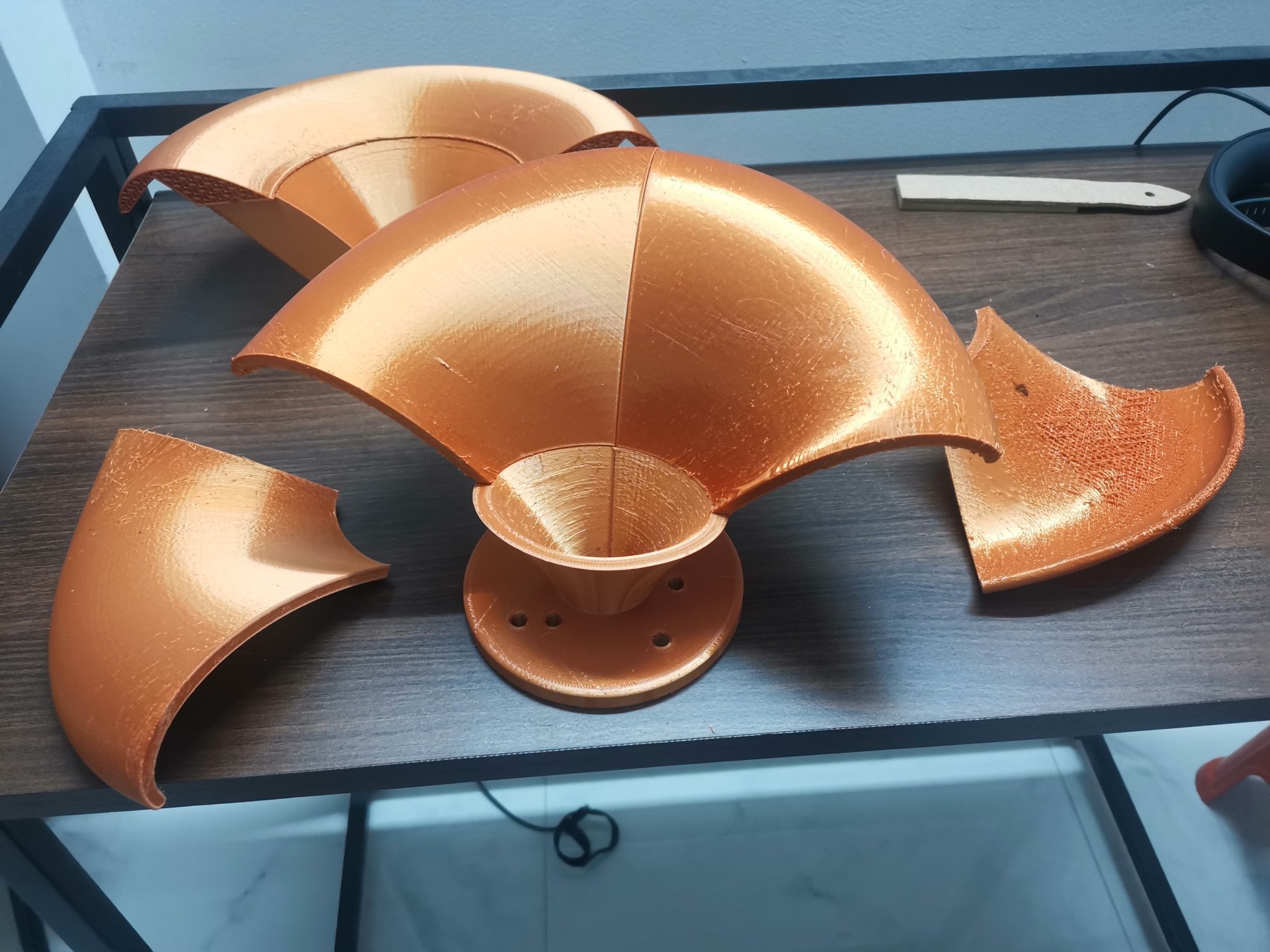
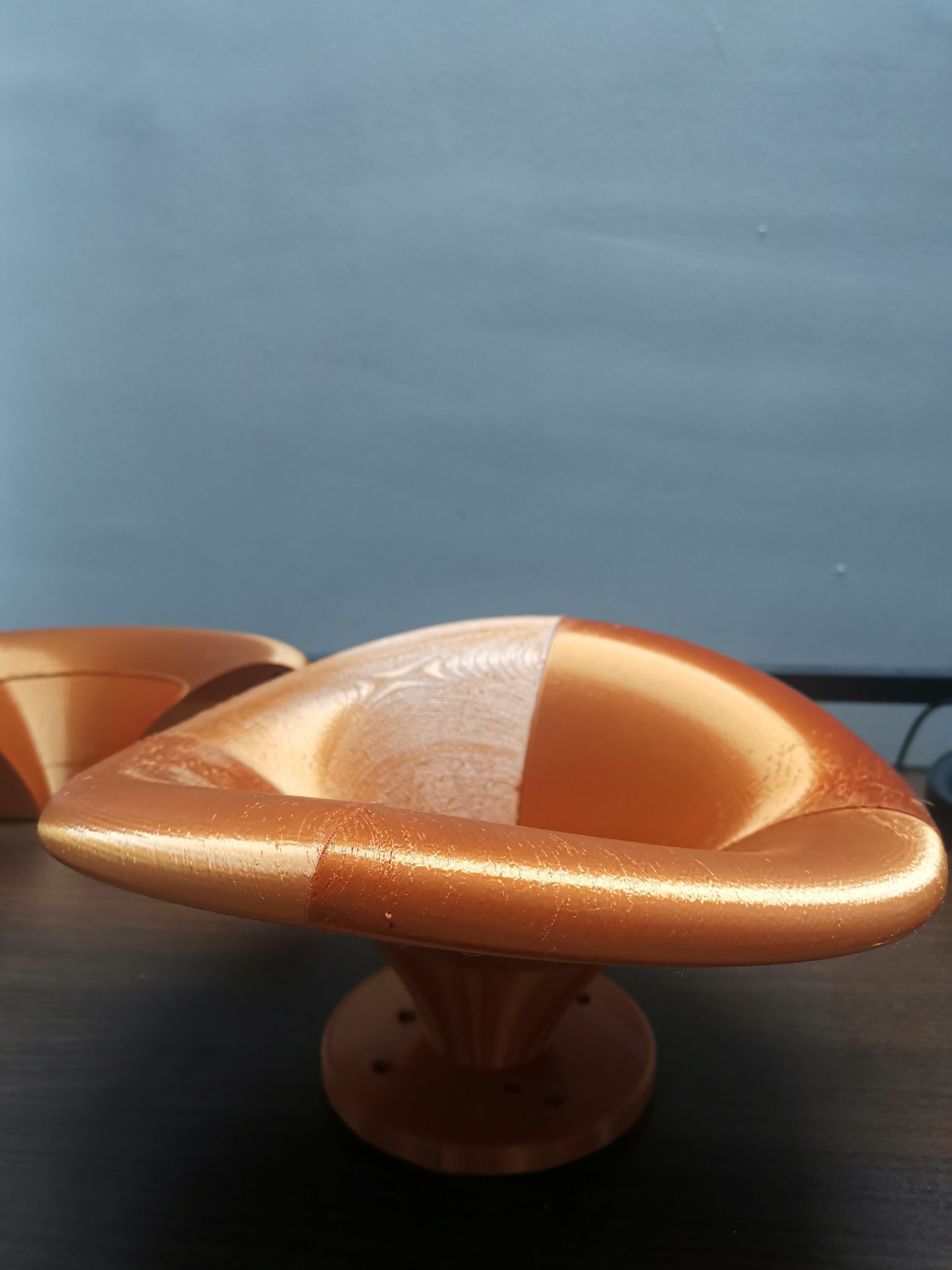
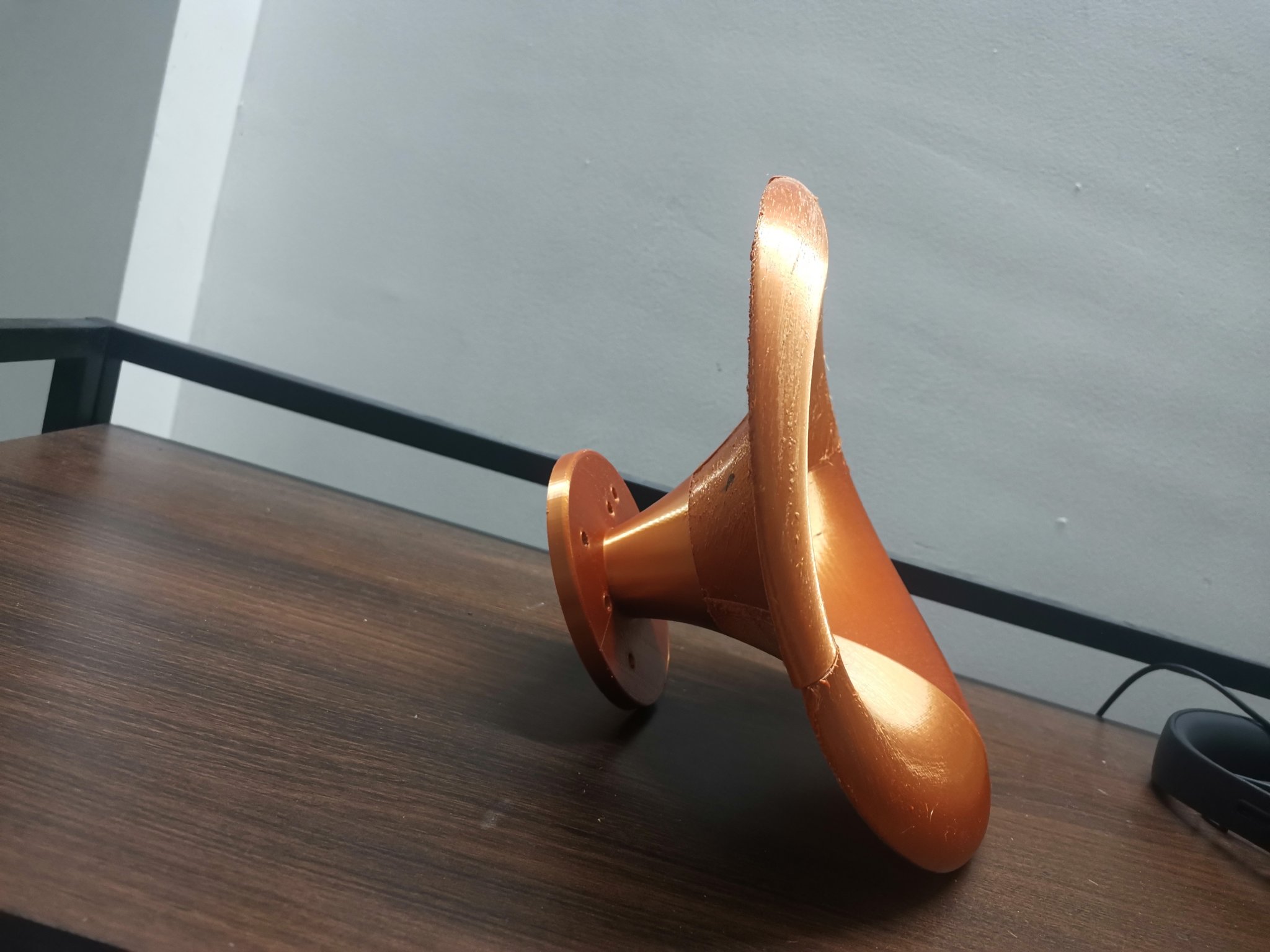
So the thing is assembled and glued with cyanoacrylate glue. If i hold it against the light, I can see minute gaps through the glued portions between the petals. I probably need to fill it up? Will these minute leaks have some effect on the overall radiation pattern of the device? Needs to be tested and seen..
All parts are printed with 15% gyroid infill. I wanted to fill up the petals but I didn't do it this time since i have to first find out what is the better available material for filling the printed parts. Something like Casting polyurethane I guess.
Anyway, due to the lack of local availability of other compression drivers that i wanted, like the 1inch SB audience Bianco-44CD-PK, for the time being i have bought a Peerless by Tymphany DFM 2544R00 compression driver to pair up with this horn and try to take some measurements.. and listen to the overall sound of it...
It is the ATH generated ST260 KVAR with 1inch throat. This was a real learning experience in 3D printing even though i would have probably wasted about 250+ gm of PLA+ filament material.
I started with the regular ST260. Fluid had given me the STL files that he had designed. I tried to print it but my printer screwed it up due to the longer print times involved due to power failure related issues in my area, support failures during printing, wrong infill settings, etc. Here is what I salvaged from the whole set of disasters. Probably a close to half of the waveguide. If this had completed properly, I would have had a much better looking and feeling waveguide than what i currently have.
Dejected by the failures, I first bought a UPS for my 3D printer, then to learn this entire thing about how to assemble a waveguide printed in parts, I decided to print the KVAR version of ST260 in 5 parts. 4 petals + 1 throat piece.
Surprisingly, I was able to print the parts and assemble it together. Again each part was a learning experience in 3D printing. Hemce the petal looks and finishing varies across the different parts..
Here are some pics of what i currently have.
So the thing is assembled and glued with cyanoacrylate glue. If i hold it against the light, I can see minute gaps through the glued portions between the petals. I probably need to fill it up? Will these minute leaks have some effect on the overall radiation pattern of the device? Needs to be tested and seen..
All parts are printed with 15% gyroid infill. I wanted to fill up the petals but I didn't do it this time since i have to first find out what is the better available material for filling the printed parts. Something like Casting polyurethane I guess.
Anyway, due to the lack of local availability of other compression drivers that i wanted, like the 1inch SB audience Bianco-44CD-PK, for the time being i have bought a Peerless by Tymphany DFM 2544R00 compression driver to pair up with this horn and try to take some measurements..
Vineethkumar01
Well-Known Member
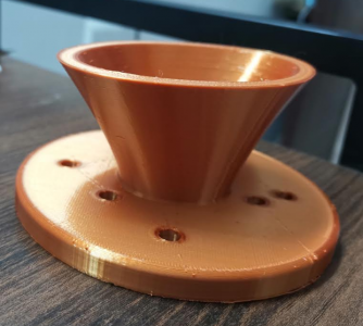
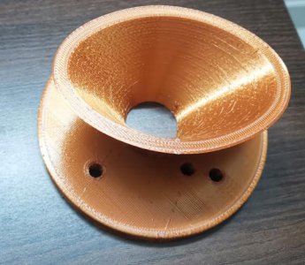
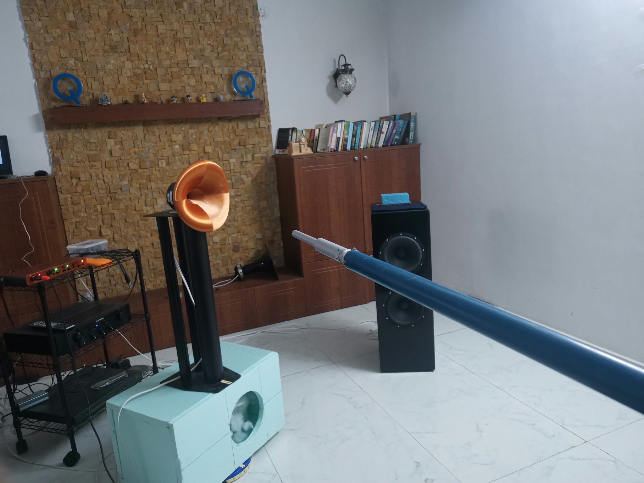
I got the Peerless DFM 2544R00 8 compression drivers today. Since one of the horns was printed out, i couldn't wait to see some measurements.. So i took an impedance sweep and horizontal polars upto 60degrees of one driver. I was going to do the full sweep but the overall rotating setup came crashing down to the floor due to the flimsiness of the base (an xps foam box) that i had kept on the turntable to raise height of the horn+driver up from the floor and due to my attempts to ensure that the horn mouth is at ths centre of the turntable.
Fortunately, it looks like the driver has survived. But the horn broke off from the base. It could be stuck together with sugerglue, I have to try or print another one.
Anyway here is what i got till now.
Setup
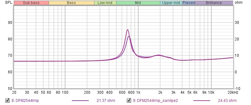
Impedance measurements of both drivers without horn
Horizontal polar upto 60 degrees with 4.06ms gate
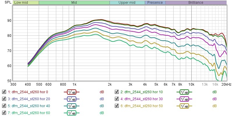
To my relatively inexperienced eyes, this driver+horn combination looks really good from the polars..
If the above polar doesn't drive home the point of what i meant earlier by saying that this device is state of the art, here is the money pic. The normalized polars from measurements above. Normalized off axes responses w. r. t the on axis measurement (no smoothing involved anywhere other than the measurement gate window width of 4.06ms. That gives a resolution of about 250Hz across the spectrum)
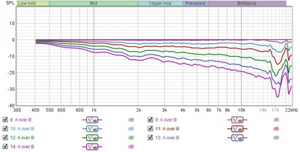
Talk about textbook perfect..
What this means is fact the response can be equalized to anything one wants.
The polars are that consistent upto greater than 15kHz. The energy radiated out by the device decreases at higher frequencies compared to the lower frequencies due to the increase in directivity which is evident from the normalized polar plots above. But this is an awesomely capable horn along with the driver..
Can this horn+driver combo be crossoved over at 1kHz?
It looks better to highpass above 1.5kHz but still I am curious..
Need to look at distortion plots though.
I have to do full polars (vertical and horizontal) but next time I do any measurement, I really need to get a better rotating turntable setup.. hmm..
Fortunately, it looks like the driver has survived. But the horn broke off from the base. It could be stuck together with sugerglue, I have to try or print another one.
Anyway here is what i got till now.
Setup
Impedance measurements of both drivers without horn
Horizontal polar upto 60 degrees with 4.06ms gate
To my relatively inexperienced eyes, this driver+horn combination looks really good from the polars..
If the above polar doesn't drive home the point of what i meant earlier by saying that this device is state of the art, here is the money pic. The normalized polars from measurements above. Normalized off axes responses w. r. t the on axis measurement (no smoothing involved anywhere other than the measurement gate window width of 4.06ms. That gives a resolution of about 250Hz across the spectrum)

Talk about textbook perfect..
What this means is fact the response can be equalized to anything one wants.
The polars are that consistent upto greater than 15kHz. The energy radiated out by the device decreases at higher frequencies compared to the lower frequencies due to the increase in directivity which is evident from the normalized polar plots above. But this is an awesomely capable horn along with the driver..
Can this horn+driver combo be crossoved over at 1kHz?
It looks better to highpass above 1.5kHz but still I am curious..
Need to look at distortion plots though.
I have to do full polars (vertical and horizontal) but next time I do any measurement, I really need to get a better rotating turntable setup.. hmm..
Last edited:
Vineethkumar01
Well-Known Member
Actually this is a typical response curve for these kind of horns/waveguides. So there is nothing wrong with the horn or the compression driver. The horn characteristics is what gives that gain of 6+dB at 2kHz compared to 10kHz. This needs to be equalized using an appropriate filter in a usage situation. The bare compression driver sensitivity is about 105+dB. Once we equalize it down to where we want (even 10dB), the curves will look perfect with plenty of sensitivity left. Typically, this is done by having (1st order) high pass filters in the 10kHz to 20kHz range.Imo 10 dB rolloff from 1 khz till 10 kHz at 0 deg horizontal is on the higher side. This happens if the CD is poorly coupled with the horn throat. If there is any offset that needs to be adjusted.
Here is some very interesting reading material about this:

Revel M105 Copy DIY build
After seeing the success of Directiva, But knowing the price, I wanted a nice small pair of passive bookshelf speakers for use in the second living room. I didn't need massive SPLs (if you need more SPLs the Directiva is much better - however that build is DSP XO + Multi Channel amplified). The...
 www.audiosciencereview.com
Well as a testimony to the capability of this horn-driver combination, if my words are not enough, here is the opinion of a guy who know a thing or two about speakers..
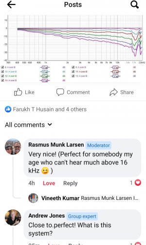
Vineethkumar01
Well-Known Member
Thank you..well done Vineeth !
regards.
My personal experience using JBL compression driver with 8" round waveguide is different though. It gives me flat response on- axis but with a hump around 2:khz with a first order filter. Using a 2 nd order filter gave me a flatter midrange and highs. The CD coupling with the horn is crucial for a flatter on-axis at 0 degActually this is a typical response curve for these kind of horns/waveguides. So there is nothing wrong with the horn or the compression driver. The horn characteristics is what gives that gain of 6+dB at 2kHz compared to 10kHz. This needs to be equalized using an appropriate filter in a usage situation. The bare compression driver sensitivity is about 105+dB. Once we equalize it down to where we want (even 10dB), the curves will look perfect with plenty of sensitivity left. Typically, this is done by having (1st order) high pass filters in the 10kHz to 20kHz range.
Here is some very interesting reading material about this:

Revel M105 Copy DIY build
After seeing the success of Directiva, But knowing the price, I wanted a nice small pair of passive bookshelf speakers for use in the second living room. I didn't need massive SPLs (if you need more SPLs the Directiva is much better - however that build is DSP XO + Multi Channel amplified). The...www.audiosciencereview.com
Well as a testimony to the capability of this horn-driver combination, if my words are not enough, here is the opinion of a guy who know a thing or two about speakers..
View attachment 70990
Vineethkumar01
Well-Known Member
I don't know about the directivity targets aimed at with the 8inch round waveguide that you are using.My personal experience using JBL compression driver with 8" round waveguide is different though. It gives me flat response on- axis but with a hump around 2:khz with a first order filter. Using a 2 nd order filter gave me a flatter midrange and highs. The CD coupling with the horn is crucial for a flatter on-axis at 0 deg
But the horn i have used is a state of the art, 26cm diameter, close to constant directivity (there is a slight increase in directivity) horn.
It is a typical response for these kind of horns as shown by BEM simulations for this horn and also as per others measurements of very similar horns. Fluid has explained this in the post i linked earlier. The pi speakers document also make this aspect very clear..
On the other hand, i do agree that horn+CD coupling is an important aspect with any design.
keechlu
New Member
Peerless driver is matching well with the horn you designed. Did you do any comparison with SB driver? 2535 and 2544 are great VFM drivers.I don't know about the directivity targets aimed at with the 8inch round waveguide that you are using.
But the horn i have used is a state of the art, 26cm diameter, close to constant directivity (there is a slight increase in directivity) horn.
It is a typical response for these kind of horns as shown by BEM simulations for this horn and also as per others measurements of very similar horns. Fluid has explained this in the post i linked earlier. The pi speakers document also make this aspect very clear..
On the other hand, i do agree that horn+CD coupling is an important aspect with any design.
Vineethkumar01
Well-Known Member
By comparison do you mean a measurement comparison of the drivers?Peerless driver is matching well with the horn you designed. Did you do any comparison with SB driver? 2535 and 2544 are great VFM drivers.
(The peerless drivers i have are 1inch throat CDs while the SB one I have is a 1.4 inch throat driver..)
I went finally with a series crossover as parallel type was getting difficult to control the 2khz hump even with a contour filter. I have to finally measure them after implementing them - one channel. I have listened whole day today and did not notice any issue- though my listening skills are not very greatly developed. Having said that, i am happy with what I listened.I don't know about the directivity targets aimed at with the 8inch round waveguide that you are using.
But the horn i have used is a state of the art, 26cm diameter, close to constant directivity (there is a slight increase in directivity) horn.
It is a typical response for these kind of horns as shown by BEM simulations for this horn and also as per others measurements of very similar horns. Fluid has explained this in the post i linked earlier. The pi speakers document also make this aspect very clear..
On the other hand, i do agree that horn+CD coupling is an important aspect with any design.
Buy from India's official online dealer!
Similar threads
- Replies
- 24
- Views
- 9K


