A 3-way active crossover design study

Vineethkumar01

Well-Known Member
Joined
May 19, 2015
Messages
473
Points
93
Location
Bangalore
Hi All,

I wanted to study designing a DSP-based 3 way crossover in VituixCAD.
I have selected the drivers for this project (I have these drivers with me) as
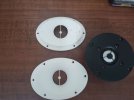
1) Satori WO24P-8 for Woofer
2) SB15CAC30-8 for midrange
3) SB26CDC-C004 as the tweeter
Since this is more of an academic exercise for now, I have generated the crossover configuration based on traced SPLs of these drivers from their datasheets ( know that ideally, we should put the drivers in the cabinet and then take measurements and then design crossover based on it)
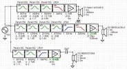
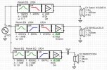
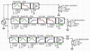
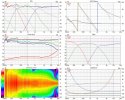
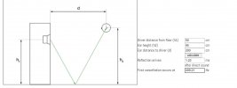
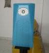
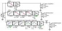
The simulations that I have attached along with this post have these drivers placed on a baffle of width 32cm and height 105 cm (with 20mm edge rounding for easing diffraction-related anomalies), currently at locations mentioned in the crossover image.
(Just for more details, the woofer is assumed to be put in sealed box of size 55L, midrange also in a sealed enclosure of about 12 L).

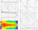
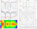
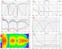
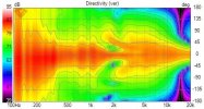
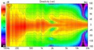
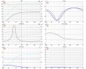
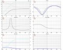
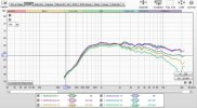
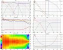
With my limited knowledge, I have tried to design a crossover for this system as shown in attached image. The vituixCAD six pack showing resultant system response details is also attached. I would like to know more details about how should I look at the driver phase matching, can I get better directivity curve for this system, get better on/off axis response etc and in general any advice to better the performance is welcome.
Looking forward to learn more from your valuable opinions.

Thanks
 

Attachments

  • 3_way_active_project_v6 XO-schema-1.jpg
    3_way_active_project_v6 XO-schema-1.jpg
    36.2 KB · Views: 71
  • 3_way_active_project_v6 Six-pack.jpg
    3_way_active_project_v6 Six-pack.jpg
    165.7 KB · Views: 70
Any reason you are only looking at LR24 on the woofer and mids and going 6db passive on the tweeters.
Secondly with the tweeters having a f/s of 690hz and good power handling capability, I would say you are wasting using it in a 3-way.
Secondly as you are going passive on the tweeters which are 4 ohms impedance in its playable bandwidth, the crossover point will be closer to 1200 hz and not 2050 if you use a 33uf capacitor.
These tweeters are better suited for a 2-way configuration.

The Satori should complement this tweeter well if you go active on both. The woofer has a flat response till around 3khz, so you can safely cross at 24db between and 1 and 2 khz without any beaming.
Mounting the woofer very close to the tweeters will help a lot.

The power handling and sensitivity between the woofer and tweeters are also reasonably close.

Good luck with the project.
Active setups are really fun to work with. Overall do the final tuning and tweaking with your ears.
Hi.. Thanks a lot for the advice. I am going full DSP-based on the crossover (on woofer, mids, and tweeter).
The design criteria that I wanted to follow in this setup is to ensure low distortion in each drivers passband and smooth directivity to the extent possible. Regarding your questions,

1) I have used fourth order electrical on the midwoofer to let it play in the region where its harmonic distortion performance is the best. For example the measurements here (https://hificompass.com/ru/speakers/measurements/sbacoustics/sb-acoustics-sb15nbac30-4) for the (almost same NBAC version) midrange driver I used above is the best in the band 200Hz to 3kHz. The acoustical crossover point in the attached plot above looks to be around 360 Hz between woofer and mid (based on the traced SPLs)

2) I also wanted to get the directivity of the mid and the tweeter to match as much as possible during the handoff. Since I have not considered the waveguided version of the tweeter, it seems it little difficult if I push the crossover between mid-tweeter higher (or I don't know yet how to do it well yet). For this I need expert advice. The capacitor on the tweeter is just there for tweeter protection with a DSP based crossover (or that was my intention after seeing this: https://www.minidsp.com/applications/digital-crossovers/digital-crossover-basics). It is not altering (supposedly) the high pass response applied on the tweeter much.

3) The mid-tweeter crossover is electrically 5th order (without considering that capacitor). The intention was to suppress the breakup of the metal cone midrange and ensure that tweeter S26CDC operates in the region where it produces minimum distortion. As per measurements here on the very similar ADC version of the tweeter that I used (https://hificompass.com/ru/speakers/measurements/sbacoustics/sb-acoustics-sb26adc-c000-4), the tweeter distortion is best above 2 kHz. The acoustical crossover point looks like happening around 2150Hz in the plot I attached above.

But, as you said, in the past there have been designs like the Helios from Jeff Bagby where a similar woofer was crossed over in between 1-2kHz with a waveguided version of another SB tweeter and it has been a very famous design. If possible, I would like to consider a 3 way design next as I already have a good two way. Hence this exercise of studying these drivers.

Thanks
 
Last edited:
ok. Understood, I presumed the section before the 33uf was the bandpass section for the mid-woofer. Guess it combines both, the bandpass n high pass of the tweeters.

If you want to try a 3-way, then why not choose a wideband driver which are widely available now.

The widebanders can take care of a wide range of frequencies (something in the range of 300hz to 12 khz). Most will not even need a bandpass as they will roll off naturally.
Then you can add a low profile tweeter with a high fs that can be crossed at above 10khz.
Thanks again.
Though I don't have any experience building 3 way speakers yet, from whatever I have read in rent forums, I agree with your suggestion that a wideband driver and a smaller tweeter might be a more popular/better choice for a 3 way.
If possible, could you please point me to a good wideband driver with similar distortion characteristics and available in India. I dont know if the famous scanspeak 10F series drivers are available in india or their price. (But I do have a pair of Tympany TC9FD18-08 drivers from a past project in hand :) )?
The main reason why I chose SB15CAC+SB26CDC was their measurably and surprisingly good distortion measurements reported by others over the years and their (or very similar drivers) documented implementations in active crossover based setups (eg: FM hifijim's system documented over at diyaudio).
I too feel that the Satori WO24P is probably wasted in a 3 way setup if used with a lower crossover point for its woofer duties. But I just considered those since I have it with me.

Regarding crossover, I think the diagrams are causing confusion. Currently,
1) I have a single LR24 filter (electrical) doing the low pass filter duty on the Woofer branch
2) I have an LR24 filter doing the high pass for the mid and a combination of two 2nd order and a single 1 st order electrical FIR filters combined, doing the high pass duty on the mid. These FIR filters have variable Q and are supposed to be linear phase. Probably, these filters will require some (50 plus?) taps to get each 2nd order roll offs?. But I am not worrying about that now since it is a DSP problem which can be handled later.
All these combined produces the bandpass response on the mid as seen in the spl plots I attached above.
3) I have a similar combination of FIR filters as above, but now doing high pass duty for the tweeter branch (unlike the kind of lowpass duty they did on the mid). Combined they are supposed to produce greater than 4th order highpass slope on the tweeter. Probably, If I had used the capacitor well, It would have increased the filter order, but since, I don't want it to affect directivity, unless somebody suggests me a better way, I don't want it to affect the response of the rest of the filter much.

Thanks
 
The main reason why I chose SB15CAC+SB26CDC was their measurably and surprisingly good distortion measurements reported by others over the years and their (or very similar drivers) documented implementations in active crossover based setups
Absolutely you should go with these. I was just giving another perspective of using a widebander.

I had built a 3-way active with Peerless 10 inch woofer, 5 inch Dayton mids and Hiquphon OW2 tweeters for my home audio. Iinitially experimented with a 7.1 soundcard and active crossover plugin built into JRIver Media Player. It was purely for experimentation and learning.
Later switched to a pro audio DBX 234xs.
This experience helped my build quite a professional 4-way active setup in my car where I used all Dayton Audio drivers from the same series with a widebander and an active head unit which had multiple crossover, attenuation options, time alignment and parametric equaliser.
Thank you.
I am also planning to implement a software-based crossover initially to learn more.
Could you let me know which is the sound card that you used.
Earlier there was ASUS XONAR external sound card at reasonable price. Now it seems to be unavailable.
Also could you let me know which multi-channel amplifier you used?
 
That said, if you can get hold of an active head unit like the Pioneer 80PRS, you will have a player with build in DSP that can play from CD, USB with a built in FM radio and also aux input.
These come with excellent Burr Brown DACs as well.

https://www.pioneerelectronics.com/PUSA/Car/CD-Receivers/DEH-80PRS

You would just need a 220/12 volt power supply and keep it on standby mode so that the memory settings are not deleted on switching off.
 
Continuing the more academic exercise of trying to better the crossover for this combination of drivers with traced SPL, here are is an updated design. The following have been presented in the 3 attached pics
1) The 1st pic in the attachment shows the topology of the DSP-based crossover.

2) The 2nd pic shows the ON-axis frequency response (mainly) in the left hand top corner. Phase response of all drivers are shown in the right hand top corner. Listening window, power response (blue), directivity (red) etc are shown in the left hand middle plot. The overall electrical filter transfer functions for the woofer, mid, and tweeter are shown on the right hand side middle plot. The overall horizontal plane directivity (which combines the on and off-axis response responses) is shown by the polar plot on the left-hand side bottom.
The approach that I took in this iteration of the design was to try to linearize the response of the drivers in their passband as much as I could with parametric EQ and try to level match drivers based on woofer response. Then I crossed over all 3 drivers with 4th order LR filters at frequencies such that the phases of the crossed over drivers track each other till (approximately) an octave above and an octave below the crossover point. Again, since this is not using measured phases of the drivers in the cabinet, I am assuming it is the minimum phase responses derived based on the magnitude responses, somehow calculated by VituixCAD.

3) The 3rd pic shows all the above details for the same crossover and drivers but with the midrange driver's polarity reversed. We can see deep nulls around crossover points in the first pic on left hand side top (ON axis responses), which is usually used to check phase matching (I think).

I still feel that this crossover can be made better by somehow tweaking the crossover such that slight 'S' curve around 3.5 kHz in the directivity plot on the left hand side middle plot of 2nd pic and slightly rising power response around the same point in the same plot can be adjusted. But I don't know how to do it as of now. Is waveguiding the tweeter necessary for narrowing the directivity in this case. I don't know. I request help from anyone who could give me suggestions to improve this or any other aspects of this crossover.

Edit:
Coming to think about this more, I feel that the linearization of driver responses is what will help us in achieving the desirable property of drivers tracking each other in phase (relative phase) over larger frequency ranges. Looks like the overall phase response of each driver (excluding the phase offsets caused by fixed delays due to relative acoustic offsets of the drivers in the cabinet) is shaped by the initial filters/parametric EQ helping it achieve flat magnitude response response. This results in a constant phase kind of response over the range of frequencies where the magnitude is linear, which is then finally shaped to track the other drivers phase responses by the crossover filters. I have heard people saying on other forums that a driver phase response will track the minimum phase response (and therefore this is the phase that we should devote more attention to in crossover design) in frequency ranges where the driver doesn't show weird behaviors like cone breakup (where the driver overall phase response will significantly differ from minimum phase).

Also, I am suspecting that if we reduce the baffle support for radiation from these kind of flat flanged tweeters through deep Avalon acoustic like chamfers (shown in attached pic), it will help in better directivity matching (at least to some extent) between tweeter and midrange driver. It will also supposedly push the baffle diffraction anomalies in tweeter response to much higher frequency ranges. These may again be smoothed by using felt pads on the baffle around tweeter etc, if at all required.

I have simplified the crossover further as shown in attached figure-1. The resulting system response is shown in figure-2.
The system response with mid reversed (to see reverse nulls) is shown in figure-3.
Figure-4 shows the vertical directivity polar plot for this configuration.

If anyone has more insights about these aspects, kindly share..

Thanks
Vineeth
 

Attachments

  • 3_way_active_project_v6.jpg
    3_way_active_project_v6.jpg
    66.5 KB · Views: 39
  • 3_way_active_project_v7 Six-pack.jpg
    3_way_active_project_v7 Six-pack.jpg
    165.5 KB · Views: 32
  • 3_way_active_project_v7 Six-pack_mid_reversed.jpg
    3_way_active_project_v7 Six-pack_mid_reversed.jpg
    171 KB · Views: 42
  • avalon speaker.jpg
    avalon speaker.jpg
    79.9 KB · Views: 53
  • 3_way_active_project_v8 XO-schema-1.jpg
    3_way_active_project_v8 XO-schema-1.jpg
    52.6 KB · Views: 38
  • 3_way_active_project_v8 Six-pack.jpg
    3_way_active_project_v8 Six-pack.jpg
    164.8 KB · Views: 25
  • 3_way_active_project_v8 Six-pack_mid_reversed.jpg
    3_way_active_project_v8 Six-pack_mid_reversed.jpg
    170.7 KB · Views: 24
  • 3_way_active_project_v8 Directivity (ver).jpg
    3_way_active_project_v8 Directivity (ver).jpg
    27.7 KB · Views: 24
Last edited by a moderator:
Another version of the crossover and probably the last till I the cabinets built and am able to take ON and off axis measurements with some accuracy. I have mainly changed the filters in the mid and tweeter branches while trying to get a better power response curve and horizontal directivity. However, all these were intended to smoothen out things in the frequency domain. EQs and delays and other filters along with the drivers will definitely have an impact on the time domain performance in terms of impulse/step responses and energy decay. Maybe I will need to reduce Qs of my filters etc in accordance with the actual measurements. Maybe, this kind of a topology will work well. Will figure out later.
For now, at least now I have a little bit of confidence about initial steps to be taken while going about the crossover in this scenario.
I have attached pics that show the following:
1) Image-1: Latest iteration of crossover
2) Image-2: Resulting on and off axis frequency responses, phase responses, directivity curves
3) Image-3: Vertical directivity plots which show the impact of vertical positioning of the drivers and the filters used
4) Image-4: Bass alignment related details for Satori WO24P-8 woofer in a sealed cabinet if volume 55L
Some additional details for this alignment given by VituixCAD:

STATISTICS
f3 48.3 Hz
f6 33.6 Hz
f10 24.5 Hz
Zmin 5.8 Ohm @ 329.4 Hz
Zmax 79.8 Ohm @ 39.4 Hz
GDmax 6.6 ms @ 17.1 Hz
XmaxC 2.5 mm @ 5 Hz
Pmax 1.4 VA @ 329.4 Hz
-------------------------------------------------------------
DRIVER: SB Acoustics SATORI WO24P-8, 1 pcs in series
n0 0.30 % Reference efficiency
SPL 87.0 dB/W Sensitivity
USPL 88.4 dB/2.83 Sensitivity
EBP 59.8 Efficiency bandwidth product
Dd 18.0 cm Effective diameter of driver
Vd 216.8 cm^3 Maximum linear volume of displacement
Cas 6.24E-7 m^5/N Acoustic equivalent of Cms
Mas 6.77E1 kg/m^4 Acoustic equivalent of Mms+Mme
Ras 1.83E3 Ns/m^5 Acoustic equivalent of Rms
Rae 2.6E4 Ns/m^5 Acoustic equivalent of Re+Rg
Lces 9.4E-2 H Electrical inductive equivalent of Cas
Cmes 4.49E-4 F Electrical capacitive equivalent of Mas
Res 8.25E1 Ohm Electrical resistive equivalent of Ras
-------------------------------------------------------------
BOX REAR 1: Vb=55.0 l, Ql=100.0
Fb 39.5 Hz System resonance frequency
Cab 3.89E-7 m^5/N Acoustic compliance of air in enclosure
Rab 1.03E2 Ns/m^5 Acoustic resistance due to absorption
Ral 1.03E6 Ns/m^5 Acoustic resistance due to leakage
Lceb 5.87E-2 H Electrical inductive equivalent of Cab
Reb 1.46E3 Ohm Electrical resistive equivalent of Rab
Rel 1.46E-1 Ohm Electrical resistive equivalent of Ral
Qtc 0.60 Total Q factor


5) Image-5: Bass alignment related details for Satori WO24P-8 woofer in a sealed cabinet if volume 45L
Some additional details for this alignment given by VituixCAD:

STATISTICS
f3 47.6 Hz
f6 34.6 Hz
f10 25.6 Hz
Zmin 5.8 Ohm @ 329.4 Hz
Zmax 78.5 Ohm @ 42.4 Hz
GDmax 6.2 ms @ 22.4 Hz
XmaxC 2.2 mm @ 5 Hz
Pmax 1.4 VA @ 329.4 Hz
-------------------------------------------------------------
DRIVER: SB Acoustics SATORI WO24P-8, 1 pcs in series
n0 0.30 % Reference efficiency
SPL 87.0 dB/W Sensitivity
USPL 88.4 dB/2.83 Sensitivity
EBP 59.8 Efficiency bandwidth product
Dd 18.0 cm Effective diameter of driver
Vd 216.8 cm^3 Maximum linear volume of displacement
Cas 6.24E-7 m^5/N Acoustic equivalent of Cms
Mas 6.77E1 kg/m^4 Acoustic equivalent of Mms+Mme
Ras 1.83E3 Ns/m^5 Acoustic equivalent of Rms
Rae 2.6E4 Ns/m^5 Acoustic equivalent of Re+Rg
Lces 9.4E-2 H Electrical inductive equivalent of Cas
Cmes 4.49E-4 F Electrical capacitive equivalent of Mas
Res 8.25E1 Ohm Electrical resistive equivalent of Ras
-------------------------------------------------------------
BOX REAR 1: Vb=45.0 l, Ql=100.0
Fb 42.1 Hz System resonance frequency
Cab 3.18E-7 m^5/N Acoustic compliance of air in enclosure
Rab 1.19E2 Ns/m^5 Acoustic resistance due to absorption
Ral 1.19E6 Ns/m^5 Acoustic resistance due to leakage
Lceb 4.8E-2 H Electrical inductive equivalent of Cab
Reb 1.27E3 Ohm Electrical resistive equivalent of Rab
Rel 1.27E-1 Ohm Electrical resistive equivalent of Ral
Qtc 0.64 Total Q factor


6) Image-6: Preliminary calculations showing the impact of woofer positioning on the baffle and the resulting comb filtering that introduces the so called floor bounce nulls in the frequency response. Image says that for a woofer located at 50cm up from the ground, for an ear height of 95cm from the floor, the first reflection-related null in the frequency response occurs at around 410Hz. This is not considered in the previous plots.
For now, I don't know if this is a serious issue of not and need guidance from someone.
Also, I need help in finalizing a sealed (hopefully, if possible, etc) bass alignment for this woofer. Example alignments were discussed above.
Hoping to get some advice on above.

Thanks
Vineeth
 

Attachments

  • 3_way_active_project_v8 XO-schema-1.jpg
    3_way_active_project_v8 XO-schema-1.jpg
    63.6 KB · Views: 23
  • 3_way_active_project_v8 Six-pack.jpg
    3_way_active_project_v8 Six-pack.jpg
    164.9 KB · Views: 23
  • 3_way_active_project_v8 Directivity (ver).jpg
    3_way_active_project_v8 Directivity (ver).jpg
    27.8 KB · Views: 17
  • SB Acoustics SATORI WO24P-8 Six-pack.jpg
    SB Acoustics SATORI WO24P-8 Six-pack.jpg
    137.6 KB · Views: 15
  • SB Acoustics SATORI WO24P-8 Six-pack_45L.jpg
    SB Acoustics SATORI WO24P-8 Six-pack_45L.jpg
    137.4 KB · Views: 15
  • floor bounce.JPG
    floor bounce.JPG
    58 KB · Views: 17
Another version of the crossover and probably the last till I the cabinets built and am able to take ON and off axis measurements with some accuracy. I have mainly changed the filters in the mid and tweeter branches while trying to get a better power response curve and horizontal directivity. However, all these were intended to smoothen out things in the frequency domain. EQs and delays and other filters along with the drivers will definitely have an impact on the time domain performance in terms of impulse/step responses and energy decay. Maybe I will need to reduce Qs of my filters etc in accordance with the actual measurements. Maybe, this kind of a topology will work well. Will figure out later.
For now, at least now I have a little bit of confidence about initial steps to be taken while going about the crossover in this scenario.
I have attached pics that show the following:
1) Image-1: Latest iteration of crossover
2) Image-2: Resulting on and off axis frequency responses, phase responses, directivity curves
3) Image-3: Vertical directivity plots which show the impact of vertical positioning of the drivers and the filters used
4) Image-4: Bass alignment related details for Satori WO24P-8 woofer in a sealed cabinet if volume 55L
Some additional details for this alignment given by VituixCAD:

STATISTICS
f3 48.3 Hz
f6 33.6 Hz
f10 24.5 Hz
Zmin 5.8 Ohm @ 329.4 Hz
Zmax 79.8 Ohm @ 39.4 Hz
GDmax 6.6 ms @ 17.1 Hz
XmaxC 2.5 mm @ 5 Hz
Pmax 1.4 VA @ 329.4 Hz
-------------------------------------------------------------
DRIVER: SB Acoustics SATORI WO24P-8, 1 pcs in series
n0 0.30 % Reference efficiency
SPL 87.0 dB/W Sensitivity
USPL 88.4 dB/2.83 Sensitivity
EBP 59.8 Efficiency bandwidth product
Dd 18.0 cm Effective diameter of driver
Vd 216.8 cm^3 Maximum linear volume of displacement
Cas 6.24E-7 m^5/N Acoustic equivalent of Cms
Mas 6.77E1 kg/m^4 Acoustic equivalent of Mms+Mme
Ras 1.83E3 Ns/m^5 Acoustic equivalent of Rms
Rae 2.6E4 Ns/m^5 Acoustic equivalent of Re+Rg
Lces 9.4E-2 H Electrical inductive equivalent of Cas
Cmes 4.49E-4 F Electrical capacitive equivalent of Mas
Res 8.25E1 Ohm Electrical resistive equivalent of Ras
-------------------------------------------------------------
BOX REAR 1: Vb=55.0 l, Ql=100.0
Fb 39.5 Hz System resonance frequency
Cab 3.89E-7 m^5/N Acoustic compliance of air in enclosure
Rab 1.03E2 Ns/m^5 Acoustic resistance due to absorption
Ral 1.03E6 Ns/m^5 Acoustic resistance due to leakage
Lceb 5.87E-2 H Electrical inductive equivalent of Cab
Reb 1.46E3 Ohm Electrical resistive equivalent of Rab
Rel 1.46E-1 Ohm Electrical resistive equivalent of Ral
Qtc 0.60 Total Q factor


5) Image-5: Bass alignment related details for Satori WO24P-8 woofer in a sealed cabinet if volume 45L
Some additional details for this alignment given by VituixCAD:

STATISTICS
f3 47.6 Hz
f6 34.6 Hz
f10 25.6 Hz
Zmin 5.8 Ohm @ 329.4 Hz
Zmax 78.5 Ohm @ 42.4 Hz
GDmax 6.2 ms @ 22.4 Hz
XmaxC 2.2 mm @ 5 Hz
Pmax 1.4 VA @ 329.4 Hz
-------------------------------------------------------------
DRIVER: SB Acoustics SATORI WO24P-8, 1 pcs in series
n0 0.30 % Reference efficiency
SPL 87.0 dB/W Sensitivity
USPL 88.4 dB/2.83 Sensitivity
EBP 59.8 Efficiency bandwidth product
Dd 18.0 cm Effective diameter of driver
Vd 216.8 cm^3 Maximum linear volume of displacement
Cas 6.24E-7 m^5/N Acoustic equivalent of Cms
Mas 6.77E1 kg/m^4 Acoustic equivalent of Mms+Mme
Ras 1.83E3 Ns/m^5 Acoustic equivalent of Rms
Rae 2.6E4 Ns/m^5 Acoustic equivalent of Re+Rg
Lces 9.4E-2 H Electrical inductive equivalent of Cas
Cmes 4.49E-4 F Electrical capacitive equivalent of Mas
Res 8.25E1 Ohm Electrical resistive equivalent of Ras
-------------------------------------------------------------
BOX REAR 1: Vb=45.0 l, Ql=100.0
Fb 42.1 Hz System resonance frequency
Cab 3.18E-7 m^5/N Acoustic compliance of air in enclosure
Rab 1.19E2 Ns/m^5 Acoustic resistance due to absorption
Ral 1.19E6 Ns/m^5 Acoustic resistance due to leakage
Lceb 4.8E-2 H Electrical inductive equivalent of Cab
Reb 1.27E3 Ohm Electrical resistive equivalent of Rab
Rel 1.27E-1 Ohm Electrical resistive equivalent of Ral
Qtc 0.64 Total Q factor


6) Image-6: Preliminary calculations showing the impact of woofer positioning on the baffle and the resulting comb filtering that introduces the so called floor bounce nulls in the frequency response. Image says that for a woofer located at 50cm up from the ground, for an ear height of 95cm from the floor, the first reflection-related null in the frequency response occurs at around 410Hz. This is not considered in the previous plots.
For now, I don't know if this is a serious issue of not and need guidance from someone.
Also, I need help in finalizing a sealed (hopefully, if possible, etc) bass alignment for this woofer. Example alignments were discussed above.
Hoping to get some advice on above.

Thanks
Vineeth
Hi, this is fairly smooth except for the upper bass hump at 200hz and continuation into the lower mid. you may want to tweak that a bit by moving the crossover points a bit and then adding delay. would not recommend changing slopes as that might create further phase issues that would need resolving.

your responses are extremely smooth. did you actually measure, or used published FRD files? If I am not missing something also dont see baffle step correction, does vituixcad not offer that as an option? if not you will need to modify your woofer .FRD to reflect BSC (or unless this is going to be flush against a wall)

all the best!
 
are you using REW exclusively or multiple software to measure the driver responces?
How are you feeding the signals to the drivers?
 
Hi, this is fairly smooth except for the upper bass hump at 200hz and continuation into the lower mid. you may want to tweak that a bit by moving the crossover points a bit and then adding delay. would not recommend changing slopes as that might create further phase issues that would need resolving.

your responses are extremely smooth. did you actually measure, or used published FRD files? If I am not missing something also dont see baffle step correction, does vituixcad not offer that as an option? if not you will need to modify your woofer .FRD to reflect BSC (or unless this is going to be flush against a wall)

all the best!
Hi,
Thanks a lot for your suggestion. I will definitely try it out.
The above plots were obtained by using the traced ON axis response from the driver datasheet (IEC baffle response measured at 31.6 cm or so as per the datasheet). put all drivers on a baffle of size 32 cm (width) by 105 cm (height).

The drivers are centered at locations specified in the crossover block diagram near the drivers (tweeter at the top (about 10 cm down from the top of the baffle, followed by midrange driver down further such that centre-to-centre (c-to-c) distance between mid and tweeter = 17cm, followed by the woofer further down such that the c-to-c between mid & woofer = 25cm). The reference point for acoustic summation is in between tweeter and mid 65cm down from tweeter and 105cm above mid at the point 2 m away from the baffle.

I have applied baffle diffraction related effects to all drivers using VituixCAD diffraction tool. I have also applied 20mm edge rounding on the above sized baffle in simulation. The OFF axis responses for all drivers were also calculated using VituixCAD diffraction tool based on the ON axis response (Therefore, all frequency magnitude and phase responses may vary when I put all these drivers on the actual baffle even if it is of the same size as mentioned above ).

This simulation exercise was to help me to study using VituixCAD to apply all these correctly and get some confidence before I actually measure the drivers on the baffle. I still have lots to learn. I intend to do actual measurements with REW/ARTA with a dayton EMM-6 Mic and ESI U86XT audio interface, which I have. I also have a MiniDSP UMIK-1 but it is not possible to do dual channel/semi dual channel measurements with it as recommended by VituixCAD.

The smoothness of the responses could be due to the edge rounding of baffle combined with thepassband linearization EQ I applied in the crossover. However, I will also double check if some smoothing is switched on inVituixCAD.

Thanks
 
are you using REW exclusively or multiple software to measure the driver responces?
How are you feeding the signals to the drivers?
Kindly refer the above reply for more details about how I got the above plots.
I am planning to take measurements in REW/ARTA once I get some foam board to make a temporary baffle first, and then again once I get the actual cabinet built.
I am planning to feed signal to drivers from REW/other software with my computer connected to the audio interface which in turn connected to the amp, which in turn would be connected to the drivers (maybe the tweeter needs special care here).
Earlier, when I used to do measurements using my UMIK-1 mic, I used to connect my computer headphone output to the amp, which were then connected to the speakers.

Thanks
 
Last edited:
I lost touch with REW now. But I remember that there is a limitation when using sound cards to take mulptile measurements due to time shift in the feed signal even when using a caliberated mic.
It needs some kind of loopback setting to adjust for this time shift using a tool called Holmimpulse.
 
I lost touch with REW now. But I remember that there is a limitation when using sound cards to take mulptile measurements due to time shift in the feed signal even when using a caliberated mic.
It needs some kind of loopback setting to adjust for this time shift using a tool called Holmimpulse.
Thanks a lot for mentioning this issue with REW. I will explore more about this.
My plan was to use ARTA/REW as per the instructions given in VituixCAD instruction manual by the Kimmo (author of Viuix CAD) here:
I will see if this works or not in my setup first and then do a troubleshooting if issues show up.
With USB MICs like UMIK-1, I haven't faced any issues with REW yet
 
Updates on the project:

As per the advice i got over at diyaudio, I am planning to add a 4 inch elliptical waveguide to my tweeter. This is supposed to help in better directivity matching, power response, and higher crossover point between mid and tweeter. Waveguides have been 3D printed. Now remains the hard tasks of attaching it to the tweeter and taking valid measurements. Hope to learn and do this process next.
 

Attachments

  • IMG_20210915_171943.jpg
    IMG_20210915_171943.jpg
    392.8 KB · Views: 40
Updates to this project

I have made a temporary baffle (or half its size height-wise (about 50cm high)), attached the tweeter to the waveguide and started studying taking on and off axis measurements with REW and a dayton EMM-6 MIC with ESI U86XT soundcard. Here are some pics of baffle, measurements and resulting frequency response measurements, over 50 degree angle (0 to 50 degree or 10 to 60 degree, I lost one of the measurements, not sure which one).
I made the baffle out of insulation foam material and carved the angular shapes/chamfers on the baffle out of it using pen knifes. The dimensions are similar to the intended final widths and final look of the baffle (at least the top half of it).
The measurements are a little bit corrupted due to reflections from somewhere. Need to figure it out. However, as of now, I am very happy with this preliminary attempt where I have been able to capture the horizontal off axis behavior of a waveguide to some extent. We can see the frequency response curves clearly separating out as the off axis angles increase and there is no bunching of curves at higher frequencies, which is one of the intended behaviors with a waveguide
Now, I am having some confidence with more measurements and finalizing box shape for building it. Next steps is to refine the measurement setup like pillows on the floor, making the transition from mic to pvc pipe seamless, better positioning of overall setup, etc etc... and bringing in VituixCAD into the workflow.

:)

Thanks
 

Attachments

  • baffle.JPG
    baffle.JPG
    45.9 KB · Views: 38
  • measurement_setup.JPG
    measurement_setup.JPG
    91.3 KB · Views: 37
  • updated_measurement.JPG
    updated_measurement.JPG
    201.9 KB · Views: 52
Last edited:
Wharfedale Linton Heritage Speakers in Red Mahogany finish at a Special Offer Price. BUY now before the price increase.
Back
Top