In one of the threads, I saw a member pose this question, ??Also the BookShelf speakers where do I need to attach them , I mean is it the Central Speaker or the Front Left and Right Speakers??. Though a manual explains most of what one needs to know, how many of us read the manual from cover to cover? That prompted me to think how hurriedly my son and I installed the 875 when we got it home, and how many mistakes we made. The rear of modern AVR's is like the control panel of Starship Entreprise. Even Captain Kirk would need the services of Spock and Scotty to unravel what is to be done.
I will try to unravel some of the issues here, and ensure that you do not make the same mistakes I made. The rear panel we are discussing here is Onkyo 576. But most AVRs have similar layouts.
Audio Video Receivers (AVRs)
Modern AVRs support either 5.1 or 7.1 layout. The Point 1 refers to what is called LFE, or Low Frequency Effects channel. This is different from a Sub Woofer out. LFE is an independent audio track that has only low frequency sounds ranging from 3-200Hz. This is sent to a special speaker called a Low Frequency Emitter or what we know as Active Sub Woofer. Why active? Because, this sub woofer will have it??s own internal amplifier.
Some AVRs also have a sub-woofer out. This carries information from all the six or seven channels that is supposed to be reproduced by the subwoofer. This information is managed by either a crossover that filters out certain frequencies, or by a sophisticated Bass Management System. The Bass Management System checks the incoming signal and directs it to a loudspeaker capable of handling it. The bass management may direct low frequency to one or more sub woofers from any channel. It does not simply redirect the contents of the LFE channel.
Thus, an LFE is NOT a sub woofer channel. But many AVRs call a LFE out as sub woofer out. Please check your manual carefully.
ROOM LAYOUT
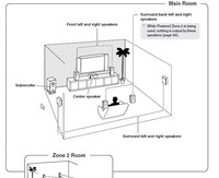
Look at the picture above. The two speakers immediately to the left and right of the TV are the FRONT Left and Right speakers, sometimes called Front L&R, which play the Front Channels. You can connect a floor stander or a bookshelf to these channels. The general rule is that the top most driver in the speaker (usually a tweeter) is at the same level as your ears in your regular sitting position.
The speaker just below the middle of the TV plays the CENTRE Channel. These are special speakers that are horizontal in shape and have two mid range drivers (or woofers) in the two edges with a tweeter in the middle. This is usually placed immediately below the TV.
The slightly largish speaker standing on the floor to the left of the TV is the sub woofer that plays the SUB WOOFER or the Point 1 LFE channel. Sub woofers are of two types ?? active and passive. Active sub woofers have their own amplifier inside, and these are used for the Point 1 LFE channel. Passive sub woofers need external amplification, and may need a Bass Management System.
If you move further towards the viewer, you will find two speakers on his left and right. These speakers are connected to the SURROUND Left and Right channels. These speakers are usually mounted on the wall some 3 feet above your seated ear position. There are two types of speakers that can be used for this. One is the standard bookshelf speaker. Some brands also call them surround speakers. The other type is called dipole speakers.

The best surround sound can be achieved by using dipole speakers for SURROUND sound channels. Dipole speakers have three or five faces in the front, the largest side faces being at an angle instead of being perpendicular to the rear face. The faces have drivers mounted on them. Sound is radiated both forward and backward producing a sound field that blends in with the front speakers while using the reflection of the rear walls to produce an ambient sound field behind you. None of the drivers face your listening position so you won??t hear the speaker's location.
The layout we discussed till now is called 5.1. There are some people who believe the SURROUND sound speakers should be behind the viewer. Though there is no harm in doing that, the way DTS and Dolby Digital encode signals, the surround sound is supposed to come from your side, not your rear.
This takes us to the speaker behind the viewer. Now look at the room layout again. You will find two more speakers directly behind the viewer. These are usually in line with the front speakers. These play the SURROUND BACK Left and Right channels. You need a 7.1 AVR to drive these speakers. These are also sometimes called SURROUND REAR Channels. The correct term is BACK.
Before we discuss other connections, let us complete the speaker connections. Most AVRs bunch the speaker connections together as shown below.
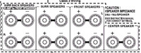
From the left, you have two sets of connections for Surround Back, Surround, and Front. At the right extreme edge you have one set for Centre Channel.
Each connection set requires a two-lead interconnect between the positive and negative terminals on your AVR / Amp and, the speaker unit.
Speaker Cables
There are a variety of speaker cables available in the market. You can buy complete speaker cables in standard lengths, or you can purchase the cables as rolls and then connect the required plugs or terminals as per your exact requirements.

A speaker cable consists of two sets of multi stranded copper wires that are individually insulated but moulded together. Most of the better brands use what is call Oxygen Free Cables or OFC cables.
Why OFC? Unalloyed copper has high electrical conductivity. Electrolytic tough-pitch (ETP) copper is an inexpensive industrial copper used for producing wire, rods and strips. ETP copper has a nominal oxygen content of about 0.04%. When ETP copper is heated above 400C, atmospheric hydrogen can diffuse into the copper and form steam. The water molecules do not diffuse easily and form internal holes. This makes the copper brittle. This process is called hydrogen embrittlement. The presence of oxygen literally adds fuel to the fire. In addition, generally oxygen is bad for copper. Copper oxidizes and turns green and flaky in the presence of oxygen. It loses its conductivity and begins to fall apart.
To avoid this, the ETP copper is cast in an oxygen removing environment. The copper produced by this method is called oxygen-free high-conductivity (OFHC) copper and is the alloy C10200. OFHC can be heated and soldered in an open environment without becoming brittle.
There are some arguments that unalloyed copper that has just 0.04% oxygen is good enough. A company called Belden Cables claims to have left one of its unalloyed copper cables outside for 25 years without any loss of conductivity. But that is another story.
Speaker cables come in what is called American Wire Gauge (AWG) which is a measure of its thickness. For normal use, the AWG specs to look for are between 16 and 12 AWG. The smaller the number, the thicker is the copper conductor, and the better its capacity to pass the amplified audio signal. If you are running long lengths (in excess 200 feet or roughly.60m), stick to 12 AWG.
If you look at a speaker cable the shield itself will be colored red (for ??ve) and black (for +ve). If they are of the same color, they will be marked (+) and (-) to help you distinguish between the two leads. If not, there will be some way to visually tell them apart. Even if there are no markers and the shielding are of the same color, don't worry. Buy two tapes, one of red color, and the other black. Cut the speaker cable of the length you need, and lay it flat on the ground. Take a lead from one end, and stick a small red tape round the edge of the shield. Leave about an inch or so, so that you can cut the shield and expose the copper wires inside. Using your hand, trace the lead to the other end of the cable and stick another red tape there. Just stick two black tapes on the two ends of the other lead. Some of the AVRs come with black and red stickers for each channel. You can either use them or use colored tapes and mark them with a marker pen.
One both ends, ie., on the AVR (or amp) end and the speaker end, the red lead goes to the red terminal, and the black lead goes to the black terminal.
The +ve and ??ve we discussed above is called polarity. Maintaining the correct polarity is important especially in a multi-channel system such as an AVR. Incorrect polarity will throw the respective speaker in an out-of-phase mode with the rest.
If you do decide to hook up your wire without connectors, use a wire stripper to take about 3/8-inch of insulation off the ends of each lead, exposing bare wire strands (be careful not to cut these strands). Twist each lead's bare wire strands tightly, so no stray strands are sticking out. Loose strands could make contact with the cable's other lead and cause a short circuit and potentially damage your gear.
Speaker Connectors
Speaker connectors are of two types. One is Spring Terminal, and the other is called Binding Post.
Spring Terminals

These have been around for a long time, and are a very inexpensive way of connecting speaker cables.
Spring terminals use spring-loaded connectors to create a compression connection around either pins or bare wire. The spring terminal connection is limited by the small size of the actual connection surface, and the fact that the connection itself is not as tight as other options. To help obtain a better connection, it is important to pull the cable slightly after it has been secured in the terminals. This will cause the teeth inside the connectors to 'bite' into the wire.
Binding Post Terminals
This is what you will find in most AVRs and high end amps.
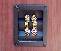
This consists of a base plate from which a screw will extend out. The screw has a cap with either a hexagonal face or with small grooves. You can untwist the cap, insert the naked cable between the base plate and the cap, and tighten the cap again. Binding posts are usually gold plated for increasing the conductivity.
Sometimes the caps also have a small hole into which you can insert a ??spade?? or a banana plug. Binding posts provide better connectivity than spring loaded terminals.
OTHER CONNECTIONS
The rear panel of the Onkyo 576 looks as shown in the following image
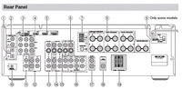
The panel has two major parts - input and output. You connect all kinds of sources through the input, and connect other items through the output.
Input sources can be both digital and analogue. These include a CDP, DVD, tape, radio, satellite, cable connection, camera, antenna etc.
Main output devices are the TV, speakers, and any recording device such as a tape recorder, CD Recorder, or DVD Recorder.
Before we move forward let use quickly look at what these numbers represent.
(1) Digital In Optical. These are for connecting a source such as a CD player or a DVD Player that has optical digital out. These use an optical cable with a TOSLINK connector.
(2) Digital In Coaxial. These are for connecting a source such as a CD player or a DVD Player that has coaxial digital out. These use a coaxial cable with a RCA connector.
(3) Component Video In. These are again for connecting any source such as a DVD player that has component out. These use three coaxial cables bundled together with RCA connectors that are usually colored Red, Yellow and White.
(4) Component Video Out. Again using the component cable we discussed above, you use these sockets to connect your AVR to the TV or projector that has a component vide input.
The component video input/out was the most popular and the best format for video connection till it was overtaken by DVI and then HDMI
(5) HDMI In and Out. HDMI (High Definition Multimedia Interface) connections carry digital audio and digital video. The HDMI inputs are for connecting units with an HDMI output, such as a DVD player. The HDMI outputs are for connecting a TV or projector that has a HDMI input.
(6) Monitor Out. The S-Video or composite video jack should be connected to a video input on your TV or projector.
(7) AM And FM Antenna. The AM push terminals are for connecting an AM antenna. The FM jack is for connecting an FM antenna. These antennas are usually supplied with the AVR.
(8) FRONT L/R, CENTER, SURROUND L/R, and SURROUND BACK L/R SPEAKERS. These terminal posts are for connecting the front, center, surround, and surround back speakers.
(11) CD In. This analog audio input is for connecting a CD player??s analog audio output. This uses a RCA connector.
(12) Tape In/Out. These analog audio input and output jacks are for connecting a recorder with an analog audio input and output, such as a cassette deck, MD recorder, etc. These use RCA connectors.
(13) Cable/Satellite In. A cable or satellite receiver can be connected here. There are S-Video and composite video input jacks for connecting the video signal, and there are analog audio input jacks for connecting the audio signal.
(14) VCR/DVR In/Out. A video component, such as a VCR or DVR, can be connected here for recording and playback. There are S-Video and composite video input and output jacks for connecting the video signal, and there are analog audio input jacks for connecting the audio signal.
(15) DVD In. This input is for connecting a DVD player. There are S-Video and composite video input jacks for connecting the video signal.
(16) DVD FRONT L/R, CENTER, SUBWOOFER, SURROUND L/R, and SURROUND BACK L/R. This analog multichannel input is for connecting a component with a 5.1/7.1-channel analog audio output, such as a DVD player, DVD-Audio or SACD-capable player, or an MPEG decoder. Depending upon whether you are using a 5.1 or a 7.1 AVR, you will have either 6 or 8 sockets here. On a DVD Player that has analogue out, you will have similar sockets. You can purchase a set of 6 or 8 RCA style cable bundled together, or use individual cables with RCA jacks. When this connection is used, all the sound decoding is expected to be done on the DVD player. The AVR becomes a simple multi channel amplifier.
(17) Zone 2 Line Out L/R. Many AVRs allow you to send data into another room called Zone 2. These analog audio outputs can be connected to the line inputs on amplifiers in Zone 2.
(18) Subwoofer Pre Out. This analog audio output can be connected to a powered subwoofer. As I explained above, this will, in many cases, be a LFE out.
(19) Zone 2 Speakers L/R. Similar to the Zone 2 Line out, some AVRs also have powered outputs for a second room. These push terminals are for connecting speakers in Zone 2.
CABLES - ANALOGUE
First let us look at the cables.
Coaxial Cable
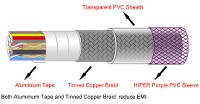
In Analogue audio, data is usually carried in what is called a dielectric or coaxial cable.
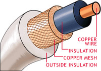
This consists of a single or multiple strands of copper wire that is enclosed in a shield. This shield is also called dielectric which is a short form of the words 'dia' and electric. 'Dia' is a Greek word meaning through. In other words, dielectric material does not allow electricity to pass through it. Over this shield is a very fine steel mesh or braid that acts as an earth. On top of this mesh is a second insulation.
S-Video
This is called Super Video or Separated Video abbreviated S-Video. It is also called Y/C. This carries only video data.

An S-Video cable has four single core copper cables individually sheathed in insulators. These are then put together in an external metal shield which in turn is covered by a tough jacket.
S-Video was originally known as "Y/C Separated video". S-Video separates the color information (Chrominance) from the brightness (Luminance) that matches the way TV display separate Luminance (Y) and Chrominance (C) signals. Thus S-Video gives much better clarity as compared to composite. S-Video carries 480i or 576i resolution video, i.e., standard definition video.
SCART Cable

SCART stands for 'Syndicat des Constructeurs d'Appareils Radiorécepteurs et Téléviseurs'. Designed in Europe, SCART has 21 individual insulated copper cables that provide connections for video input and output, audio input and output, RGB video and control signals (2 communications data connections, blanking, function switching). SCART is a two way system - meaning the two devices on both ends can talk to each other. A SCART connection has 20 pins, and the shield itself uses the 21st cable which is also called a braiding cable.
CABLES - DIGITAL
Digital cables are of two types - coaxial and optical.
Digital Coaxial cables are the same as analogue cables and use RCA connectors at both ends. They just carry digital data instead of analogue data.
Optical Digital Cables
These are also called S/PDIF, (for Sony/Philips Digital Interface). Optical cables do not use copper but a small hollow tube (called an optical core) that carries pulses of light.
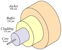
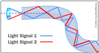
Optical cables can carry data over long lengths. The signals travel bouncing off the walls of the tube as shown in the second picture. This happens when the cable is bent a bit which is common in most installations.
The signal does not degrade, nor does it lose its strengths. Optical cables deliver one of the best reproductions of digital signals. Optical cables uses a special connector called TOSLINK. The only disadvantage of optical cables is that they do not work well when bent. They should be as straight as possible. If you require a set up that has right angles or that snakes through a room, stick with the coaxial digital cables.
HDMI
Modern TVs (HDTVs) are digital. As compared to standard TVs, HDTVs have a wider screen, more pixels and a faster refresh rate. Often, HDTVs can display more colors than older sets. This means that HDTVs need more data and need it a lot faster than standard-definition TVs do. If an HDTV can receive this information digitally, it also saves a lot of processing power and time.
High Definition Multimedia Interface (HDMI) was created to resolve this issue. HDMI supports every video format in the consumer electronics industry, plus a broad range of digital audio formats including Dolby® Digital, DTS, DTS-EX, DVD Audio, and SACD, as well as the latest high-bitrate, lossless formats, Dolby TrueHD and DTS-HD Master Audio.
HDMI Signals
HDMI uses transition minimized differential signaling (TMDS) to move information from one place to another. TMDS is a way of encoding the signal to protect it from degrading as it travels down the length of the cable. Here's what happens:
HDMI Cable:
An HDMI cables consists of 19 individual shielded cables clubbed together and again shielded
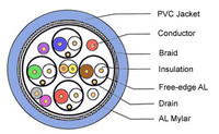
The individual cables consist of twisted pairs of copper cable and single cables. Three audio and video channels travel through three twisted pairs. The TMDS clock, which allows devices to synchronize the incoming data, travels through another twisted pair. Each of these four total pairs has a shield -- another wire that protects it from interference from its neighbors. The TMDS channels, the clock and the shields make up the bulk of the cable pairs inside the HDMI cable.
The other signals need only a single copper cable. One such channel is the consumer electronics channel (CEC). If your devices support it, this channel allows them to send instructions to one another. For example, a DVD player could automatically turn on a home-theater receiver and a TV when it starts playing a disk.
Another channel is the hot plug detect channel, which senses when you plug in or unplug a device, re-initializing the HDMI link if necessary.
Another is the display data channel (DDC) that carries device information and the HDCP encryption information. Other channels carry encryption data and electricity to power communication between devices.
HDMI cables themselves come in two categories. Category 1 has a speed of 74.25 MHz. Category 2 has a speeded of 340 MHz. Most consumer cables use the second variety.
CONNECTORS & CONNECTIONS
Audio Connectors
Audio connections are either analogue or digital.
Analog connections consist of RCA or BNC coaxial stereo connectors. These have a separate two-channel cable connection - one for the left and the other for the right signal.
Digital audio interconnections may use either a single coaxial connection or a single optical connection - also known as TOSLINK. The word TOSLINK comes from Toshiba Link. Toshiba was the first to introduce that type of connections.
Optical connections use fiber-optic cables to transfer audio signals via pulses of light from a digital source.
RCA Connectors
These are the most common type of connectors that are used for all audio input and output. These are color coded for easy identification. For example, the connectors are color coded as red for +ve and black (or white) for -ve. RCA connectors are good for Audio CD, DVD-Audio, and stereo playback.
Many of the good RCA connectors are gold plated to ensure corrosion free connections and a longer life
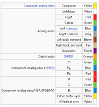
RCA Color Scheme:
RCA connectors are also used for composite analogue video, component analogue video, analog audio, and digital audio. Each of these connections have a particular color scheme. The following tables shows the color schemes followed.
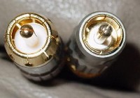
BNC Connectors
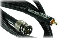
Though this may use the same coaxial or dielectric cable as the RCA, BNC connectors are more secure as they have locking mechanism where the male connector clicks into place. This is also called bayonet-style locking connector. BNC connectors are used in professional gear and high-end consumer audio and video systems. The picture above shows a BNC on one side and a RCA on another side.
TOSLINK
A TOSLINK connector is used on both sides of an optical cable.
The connector (male) consists of an end that is nearly square in shape. This also has a small tube like projection. This projection is where the optical fiber is terminated inside the connector. On the player or amplifier, there will be a socket into which this connector can fit in, in only one way. The connector and the cable are very light in weight and have to be handled carefully. When not in use, the sockets have to be covered with a plug provided, and the connectors kept inside plastic jackets that will be provided. The reason is that a little bit of dust could affect the transmission of light pulses.
VIDEO CONNECTORS
Video connectors are again analogue and digital.
Video Connectors - Analogue
RCA and BNC are also used for video transmission. In addition special connectors have been created for some of the cables we discussed above.
RF Connector
This is not strictly a video connector, but is used for that purpose quite a lot. A RF connector is an electrical connector that uses a coaxial cable. It is designed to carry Radio Frequencies.
The connectors look similar to a RCA, but have better fastening mechanism that could be thread, bayonet, braces, or a pull push. The RF connectors are used to connect a TV antenna, a cable or ever DTH connection to either your AVR or the TV directly.
Composite Video
This consists of a set of three coaxial cable terminated with RCA connectors.
The yellow carries composite video, while the red and white carry audio.
Component Video
Component video again uses RCA connectors, and consists of three color coded connectors.
Component is also called Y-Pb-Pr sometimes. The Y is Luminance, Pb for Chrominance 1, and Pr for Chrominance. Component connection provides one luminance signal with full horizontal resolution and two color signals with reduced horizontal resolution. This was the best form of connection till DVI and HDMI came in. Even today this is very good for HDTV and progressive images.
Component video does not carry any audio signals.
S-Video Connectors

The 4-pin mini-DIN connector (shown above) is the most common of several S-Video connector types. Other S-Video connector variants include 7-pin locking "dub" connectors used on many professional S-VHS machines, and dual "Y" and "C" BNC connectors, often used for S-Video patch bays. Early Y/C video monitors often used RCA connectors that were switchable between Y/C and composite video input. Though the connectors are different, the Y/C signals for all types are compatible. Like Component, S-Video does not carry any audio signals.
PREFERRED ORDER FOR CONNECTIONS.
One question that many people will have is which is the best connection? I am listing below the order of connections from the worst to the best:
Audio Connections:
Video Connections
I have not discussed DVI or IEEE-1394 as they are mostly unused.
Cheers
I will try to unravel some of the issues here, and ensure that you do not make the same mistakes I made. The rear panel we are discussing here is Onkyo 576. But most AVRs have similar layouts.
Audio Video Receivers (AVRs)
Modern AVRs support either 5.1 or 7.1 layout. The Point 1 refers to what is called LFE, or Low Frequency Effects channel. This is different from a Sub Woofer out. LFE is an independent audio track that has only low frequency sounds ranging from 3-200Hz. This is sent to a special speaker called a Low Frequency Emitter or what we know as Active Sub Woofer. Why active? Because, this sub woofer will have it??s own internal amplifier.
Some AVRs also have a sub-woofer out. This carries information from all the six or seven channels that is supposed to be reproduced by the subwoofer. This information is managed by either a crossover that filters out certain frequencies, or by a sophisticated Bass Management System. The Bass Management System checks the incoming signal and directs it to a loudspeaker capable of handling it. The bass management may direct low frequency to one or more sub woofers from any channel. It does not simply redirect the contents of the LFE channel.
Thus, an LFE is NOT a sub woofer channel. But many AVRs call a LFE out as sub woofer out. Please check your manual carefully.
ROOM LAYOUT

Look at the picture above. The two speakers immediately to the left and right of the TV are the FRONT Left and Right speakers, sometimes called Front L&R, which play the Front Channels. You can connect a floor stander or a bookshelf to these channels. The general rule is that the top most driver in the speaker (usually a tweeter) is at the same level as your ears in your regular sitting position.
The speaker just below the middle of the TV plays the CENTRE Channel. These are special speakers that are horizontal in shape and have two mid range drivers (or woofers) in the two edges with a tweeter in the middle. This is usually placed immediately below the TV.
The slightly largish speaker standing on the floor to the left of the TV is the sub woofer that plays the SUB WOOFER or the Point 1 LFE channel. Sub woofers are of two types ?? active and passive. Active sub woofers have their own amplifier inside, and these are used for the Point 1 LFE channel. Passive sub woofers need external amplification, and may need a Bass Management System.
If you move further towards the viewer, you will find two speakers on his left and right. These speakers are connected to the SURROUND Left and Right channels. These speakers are usually mounted on the wall some 3 feet above your seated ear position. There are two types of speakers that can be used for this. One is the standard bookshelf speaker. Some brands also call them surround speakers. The other type is called dipole speakers.

The best surround sound can be achieved by using dipole speakers for SURROUND sound channels. Dipole speakers have three or five faces in the front, the largest side faces being at an angle instead of being perpendicular to the rear face. The faces have drivers mounted on them. Sound is radiated both forward and backward producing a sound field that blends in with the front speakers while using the reflection of the rear walls to produce an ambient sound field behind you. None of the drivers face your listening position so you won??t hear the speaker's location.
The layout we discussed till now is called 5.1. There are some people who believe the SURROUND sound speakers should be behind the viewer. Though there is no harm in doing that, the way DTS and Dolby Digital encode signals, the surround sound is supposed to come from your side, not your rear.
This takes us to the speaker behind the viewer. Now look at the room layout again. You will find two more speakers directly behind the viewer. These are usually in line with the front speakers. These play the SURROUND BACK Left and Right channels. You need a 7.1 AVR to drive these speakers. These are also sometimes called SURROUND REAR Channels. The correct term is BACK.
Before we discuss other connections, let us complete the speaker connections. Most AVRs bunch the speaker connections together as shown below.

From the left, you have two sets of connections for Surround Back, Surround, and Front. At the right extreme edge you have one set for Centre Channel.
Each connection set requires a two-lead interconnect between the positive and negative terminals on your AVR / Amp and, the speaker unit.
Speaker Cables
There are a variety of speaker cables available in the market. You can buy complete speaker cables in standard lengths, or you can purchase the cables as rolls and then connect the required plugs or terminals as per your exact requirements.

A speaker cable consists of two sets of multi stranded copper wires that are individually insulated but moulded together. Most of the better brands use what is call Oxygen Free Cables or OFC cables.
Why OFC? Unalloyed copper has high electrical conductivity. Electrolytic tough-pitch (ETP) copper is an inexpensive industrial copper used for producing wire, rods and strips. ETP copper has a nominal oxygen content of about 0.04%. When ETP copper is heated above 400C, atmospheric hydrogen can diffuse into the copper and form steam. The water molecules do not diffuse easily and form internal holes. This makes the copper brittle. This process is called hydrogen embrittlement. The presence of oxygen literally adds fuel to the fire. In addition, generally oxygen is bad for copper. Copper oxidizes and turns green and flaky in the presence of oxygen. It loses its conductivity and begins to fall apart.
To avoid this, the ETP copper is cast in an oxygen removing environment. The copper produced by this method is called oxygen-free high-conductivity (OFHC) copper and is the alloy C10200. OFHC can be heated and soldered in an open environment without becoming brittle.
There are some arguments that unalloyed copper that has just 0.04% oxygen is good enough. A company called Belden Cables claims to have left one of its unalloyed copper cables outside for 25 years without any loss of conductivity. But that is another story.
Speaker cables come in what is called American Wire Gauge (AWG) which is a measure of its thickness. For normal use, the AWG specs to look for are between 16 and 12 AWG. The smaller the number, the thicker is the copper conductor, and the better its capacity to pass the amplified audio signal. If you are running long lengths (in excess 200 feet or roughly.60m), stick to 12 AWG.
If you look at a speaker cable the shield itself will be colored red (for ??ve) and black (for +ve). If they are of the same color, they will be marked (+) and (-) to help you distinguish between the two leads. If not, there will be some way to visually tell them apart. Even if there are no markers and the shielding are of the same color, don't worry. Buy two tapes, one of red color, and the other black. Cut the speaker cable of the length you need, and lay it flat on the ground. Take a lead from one end, and stick a small red tape round the edge of the shield. Leave about an inch or so, so that you can cut the shield and expose the copper wires inside. Using your hand, trace the lead to the other end of the cable and stick another red tape there. Just stick two black tapes on the two ends of the other lead. Some of the AVRs come with black and red stickers for each channel. You can either use them or use colored tapes and mark them with a marker pen.
One both ends, ie., on the AVR (or amp) end and the speaker end, the red lead goes to the red terminal, and the black lead goes to the black terminal.
The +ve and ??ve we discussed above is called polarity. Maintaining the correct polarity is important especially in a multi-channel system such as an AVR. Incorrect polarity will throw the respective speaker in an out-of-phase mode with the rest.
If you do decide to hook up your wire without connectors, use a wire stripper to take about 3/8-inch of insulation off the ends of each lead, exposing bare wire strands (be careful not to cut these strands). Twist each lead's bare wire strands tightly, so no stray strands are sticking out. Loose strands could make contact with the cable's other lead and cause a short circuit and potentially damage your gear.
Speaker Connectors
Speaker connectors are of two types. One is Spring Terminal, and the other is called Binding Post.
Spring Terminals

These have been around for a long time, and are a very inexpensive way of connecting speaker cables.
Spring terminals use spring-loaded connectors to create a compression connection around either pins or bare wire. The spring terminal connection is limited by the small size of the actual connection surface, and the fact that the connection itself is not as tight as other options. To help obtain a better connection, it is important to pull the cable slightly after it has been secured in the terminals. This will cause the teeth inside the connectors to 'bite' into the wire.
Binding Post Terminals
This is what you will find in most AVRs and high end amps.

This consists of a base plate from which a screw will extend out. The screw has a cap with either a hexagonal face or with small grooves. You can untwist the cap, insert the naked cable between the base plate and the cap, and tighten the cap again. Binding posts are usually gold plated for increasing the conductivity.
Sometimes the caps also have a small hole into which you can insert a ??spade?? or a banana plug. Binding posts provide better connectivity than spring loaded terminals.
OTHER CONNECTIONS
The rear panel of the Onkyo 576 looks as shown in the following image

The panel has two major parts - input and output. You connect all kinds of sources through the input, and connect other items through the output.
Input sources can be both digital and analogue. These include a CDP, DVD, tape, radio, satellite, cable connection, camera, antenna etc.
Main output devices are the TV, speakers, and any recording device such as a tape recorder, CD Recorder, or DVD Recorder.
Before we move forward let use quickly look at what these numbers represent.
(1) Digital In Optical. These are for connecting a source such as a CD player or a DVD Player that has optical digital out. These use an optical cable with a TOSLINK connector.
(2) Digital In Coaxial. These are for connecting a source such as a CD player or a DVD Player that has coaxial digital out. These use a coaxial cable with a RCA connector.
(3) Component Video In. These are again for connecting any source such as a DVD player that has component out. These use three coaxial cables bundled together with RCA connectors that are usually colored Red, Yellow and White.
(4) Component Video Out. Again using the component cable we discussed above, you use these sockets to connect your AVR to the TV or projector that has a component vide input.
The component video input/out was the most popular and the best format for video connection till it was overtaken by DVI and then HDMI
(5) HDMI In and Out. HDMI (High Definition Multimedia Interface) connections carry digital audio and digital video. The HDMI inputs are for connecting units with an HDMI output, such as a DVD player. The HDMI outputs are for connecting a TV or projector that has a HDMI input.
(6) Monitor Out. The S-Video or composite video jack should be connected to a video input on your TV or projector.
(7) AM And FM Antenna. The AM push terminals are for connecting an AM antenna. The FM jack is for connecting an FM antenna. These antennas are usually supplied with the AVR.
(8) FRONT L/R, CENTER, SURROUND L/R, and SURROUND BACK L/R SPEAKERS. These terminal posts are for connecting the front, center, surround, and surround back speakers.
(11) CD In. This analog audio input is for connecting a CD player??s analog audio output. This uses a RCA connector.
(12) Tape In/Out. These analog audio input and output jacks are for connecting a recorder with an analog audio input and output, such as a cassette deck, MD recorder, etc. These use RCA connectors.
(13) Cable/Satellite In. A cable or satellite receiver can be connected here. There are S-Video and composite video input jacks for connecting the video signal, and there are analog audio input jacks for connecting the audio signal.
(14) VCR/DVR In/Out. A video component, such as a VCR or DVR, can be connected here for recording and playback. There are S-Video and composite video input and output jacks for connecting the video signal, and there are analog audio input jacks for connecting the audio signal.
(15) DVD In. This input is for connecting a DVD player. There are S-Video and composite video input jacks for connecting the video signal.
(16) DVD FRONT L/R, CENTER, SUBWOOFER, SURROUND L/R, and SURROUND BACK L/R. This analog multichannel input is for connecting a component with a 5.1/7.1-channel analog audio output, such as a DVD player, DVD-Audio or SACD-capable player, or an MPEG decoder. Depending upon whether you are using a 5.1 or a 7.1 AVR, you will have either 6 or 8 sockets here. On a DVD Player that has analogue out, you will have similar sockets. You can purchase a set of 6 or 8 RCA style cable bundled together, or use individual cables with RCA jacks. When this connection is used, all the sound decoding is expected to be done on the DVD player. The AVR becomes a simple multi channel amplifier.
(17) Zone 2 Line Out L/R. Many AVRs allow you to send data into another room called Zone 2. These analog audio outputs can be connected to the line inputs on amplifiers in Zone 2.
(18) Subwoofer Pre Out. This analog audio output can be connected to a powered subwoofer. As I explained above, this will, in many cases, be a LFE out.
(19) Zone 2 Speakers L/R. Similar to the Zone 2 Line out, some AVRs also have powered outputs for a second room. These push terminals are for connecting speakers in Zone 2.
CABLES - ANALOGUE
First let us look at the cables.
Coaxial Cable
In Analogue audio, data is usually carried in what is called a dielectric or coaxial cable.

This consists of a single or multiple strands of copper wire that is enclosed in a shield. This shield is also called dielectric which is a short form of the words 'dia' and electric. 'Dia' is a Greek word meaning through. In other words, dielectric material does not allow electricity to pass through it. Over this shield is a very fine steel mesh or braid that acts as an earth. On top of this mesh is a second insulation.
S-Video
This is called Super Video or Separated Video abbreviated S-Video. It is also called Y/C. This carries only video data.

An S-Video cable has four single core copper cables individually sheathed in insulators. These are then put together in an external metal shield which in turn is covered by a tough jacket.
S-Video was originally known as "Y/C Separated video". S-Video separates the color information (Chrominance) from the brightness (Luminance) that matches the way TV display separate Luminance (Y) and Chrominance (C) signals. Thus S-Video gives much better clarity as compared to composite. S-Video carries 480i or 576i resolution video, i.e., standard definition video.
SCART Cable

SCART stands for 'Syndicat des Constructeurs d'Appareils Radiorécepteurs et Téléviseurs'. Designed in Europe, SCART has 21 individual insulated copper cables that provide connections for video input and output, audio input and output, RGB video and control signals (2 communications data connections, blanking, function switching). SCART is a two way system - meaning the two devices on both ends can talk to each other. A SCART connection has 20 pins, and the shield itself uses the 21st cable which is also called a braiding cable.
CABLES - DIGITAL
Digital cables are of two types - coaxial and optical.
Digital Coaxial cables are the same as analogue cables and use RCA connectors at both ends. They just carry digital data instead of analogue data.
Optical Digital Cables
These are also called S/PDIF, (for Sony/Philips Digital Interface). Optical cables do not use copper but a small hollow tube (called an optical core) that carries pulses of light.


Optical cables can carry data over long lengths. The signals travel bouncing off the walls of the tube as shown in the second picture. This happens when the cable is bent a bit which is common in most installations.
The signal does not degrade, nor does it lose its strengths. Optical cables deliver one of the best reproductions of digital signals. Optical cables uses a special connector called TOSLINK. The only disadvantage of optical cables is that they do not work well when bent. They should be as straight as possible. If you require a set up that has right angles or that snakes through a room, stick with the coaxial digital cables.
HDMI
Modern TVs (HDTVs) are digital. As compared to standard TVs, HDTVs have a wider screen, more pixels and a faster refresh rate. Often, HDTVs can display more colors than older sets. This means that HDTVs need more data and need it a lot faster than standard-definition TVs do. If an HDTV can receive this information digitally, it also saves a lot of processing power and time.
High Definition Multimedia Interface (HDMI) was created to resolve this issue. HDMI supports every video format in the consumer electronics industry, plus a broad range of digital audio formats including Dolby® Digital, DTS, DTS-EX, DVD Audio, and SACD, as well as the latest high-bitrate, lossless formats, Dolby TrueHD and DTS-HD Master Audio.
HDMI Signals
HDMI uses transition minimized differential signaling (TMDS) to move information from one place to another. TMDS is a way of encoding the signal to protect it from degrading as it travels down the length of the cable. Here's what happens:
- The sending device, such as a DVD player, encodes the signal to reduce the number of transitions between one (on) and zero (off). Think of each transition as a sharp drop-off -- as the signal travels, this drop-off can begin to wear away, degrading the signal. The encoding step helps protect signal quality by reducing the number of chances for the signal to degrade.
- One of the cables in the twisted pair carries the signal itself. The other carries an inverse copy of the signal.
- The receiving device, such as a TV, decodes the signal. It measures the differential, or the difference between the signal and its inverse. It uses this information to compensate for any loss of signal along the way.
HDMI Cable:
An HDMI cables consists of 19 individual shielded cables clubbed together and again shielded


The individual cables consist of twisted pairs of copper cable and single cables. Three audio and video channels travel through three twisted pairs. The TMDS clock, which allows devices to synchronize the incoming data, travels through another twisted pair. Each of these four total pairs has a shield -- another wire that protects it from interference from its neighbors. The TMDS channels, the clock and the shields make up the bulk of the cable pairs inside the HDMI cable.
The other signals need only a single copper cable. One such channel is the consumer electronics channel (CEC). If your devices support it, this channel allows them to send instructions to one another. For example, a DVD player could automatically turn on a home-theater receiver and a TV when it starts playing a disk.
Another channel is the hot plug detect channel, which senses when you plug in or unplug a device, re-initializing the HDMI link if necessary.
Another is the display data channel (DDC) that carries device information and the HDCP encryption information. Other channels carry encryption data and electricity to power communication between devices.
HDMI cables themselves come in two categories. Category 1 has a speed of 74.25 MHz. Category 2 has a speeded of 340 MHz. Most consumer cables use the second variety.
CONNECTORS & CONNECTIONS
Audio Connectors
Audio connections are either analogue or digital.
Analog connections consist of RCA or BNC coaxial stereo connectors. These have a separate two-channel cable connection - one for the left and the other for the right signal.
Digital audio interconnections may use either a single coaxial connection or a single optical connection - also known as TOSLINK. The word TOSLINK comes from Toshiba Link. Toshiba was the first to introduce that type of connections.
Optical connections use fiber-optic cables to transfer audio signals via pulses of light from a digital source.
RCA Connectors

These are the most common type of connectors that are used for all audio input and output. These are color coded for easy identification. For example, the connectors are color coded as red for +ve and black (or white) for -ve. RCA connectors are good for Audio CD, DVD-Audio, and stereo playback.
Many of the good RCA connectors are gold plated to ensure corrosion free connections and a longer life
RCA Color Scheme:
RCA connectors are also used for composite analogue video, component analogue video, analog audio, and digital audio. Each of these connections have a particular color scheme. The following tables shows the color schemes followed.

BNC Connectors

Though this may use the same coaxial or dielectric cable as the RCA, BNC connectors are more secure as they have locking mechanism where the male connector clicks into place. This is also called bayonet-style locking connector. BNC connectors are used in professional gear and high-end consumer audio and video systems. The picture above shows a BNC on one side and a RCA on another side.
TOSLINK
A TOSLINK connector is used on both sides of an optical cable.

The connector (male) consists of an end that is nearly square in shape. This also has a small tube like projection. This projection is where the optical fiber is terminated inside the connector. On the player or amplifier, there will be a socket into which this connector can fit in, in only one way. The connector and the cable are very light in weight and have to be handled carefully. When not in use, the sockets have to be covered with a plug provided, and the connectors kept inside plastic jackets that will be provided. The reason is that a little bit of dust could affect the transmission of light pulses.
VIDEO CONNECTORS
Video connectors are again analogue and digital.
Video Connectors - Analogue
RCA and BNC are also used for video transmission. In addition special connectors have been created for some of the cables we discussed above.
RF Connector
This is not strictly a video connector, but is used for that purpose quite a lot. A RF connector is an electrical connector that uses a coaxial cable. It is designed to carry Radio Frequencies.

The connectors look similar to a RCA, but have better fastening mechanism that could be thread, bayonet, braces, or a pull push. The RF connectors are used to connect a TV antenna, a cable or ever DTH connection to either your AVR or the TV directly.
Composite Video
This consists of a set of three coaxial cable terminated with RCA connectors.

The yellow carries composite video, while the red and white carry audio.
Component Video
Component video again uses RCA connectors, and consists of three color coded connectors.

Component is also called Y-Pb-Pr sometimes. The Y is Luminance, Pb for Chrominance 1, and Pr for Chrominance. Component connection provides one luminance signal with full horizontal resolution and two color signals with reduced horizontal resolution. This was the best form of connection till DVI and HDMI came in. Even today this is very good for HDTV and progressive images.
Component video does not carry any audio signals.
S-Video Connectors

The 4-pin mini-DIN connector (shown above) is the most common of several S-Video connector types. Other S-Video connector variants include 7-pin locking "dub" connectors used on many professional S-VHS machines, and dual "Y" and "C" BNC connectors, often used for S-Video patch bays. Early Y/C video monitors often used RCA connectors that were switchable between Y/C and composite video input. Though the connectors are different, the Y/C signals for all types are compatible. Like Component, S-Video does not carry any audio signals.
PREFERRED ORDER FOR CONNECTIONS.
One question that many people will have is which is the best connection? I am listing below the order of connections from the worst to the best:
Audio Connections:
- Analog left/right - Standard audio hookup; red/white RCA connectors.
- Optical Digital - better than analog, same quality as coaxial; red light shines through ends when in use.
- Coaxial - better than analog, similar quality as optical; typically orange RCA connector on each end.
- 5.1 channel input - superior when connecting DVD-Audio or SACD; 5 RCA-terminated cables.
- HDMI - carries both audio and video.
Video Connections
- 75-Ohm Coaxial RF connection - worst connection; familiar screw on type wire used in many homes for cable TV service.
- Composite - better than RF; single yellow RCA cable.
- S-Video - Better than RF & composite; usually black cable with pins on both ends.
- Component connection - better than RF, composite, & S-video; cable with red, blue, green connectors on both ends.
- RGB - Used mostly for computers.
- DVI - Better than component. DVI has been pushed aside by HDMI.
- HDMI - Same quality as DVI, smaller physical connector. HDMI is the best connection in the market today.
- IEEE-1394 (Firewire) - Simplified connection, but largely unused.
I have not discussed DVI or IEEE-1394 as they are mostly unused.
Cheers
")

