DIY input selector with ON-OFF-ON switch question.

Now I have three input to select from. The current arrangement allows me to select between only two.
I have 1 pole 12 way rotary switch like this .
The rotary has 12 switch positions. It got 12 outer poles and 1 middle pole.
will I be able to use that for my need?

Or do I go with https://www.gtechaudios.com/index.php?route=product/product&product_id=82?


Yes, you can wire your 1 pole 12 way rotary switch for your application ...but it will be sufficient for only 1 channel.

If u plan to use it for stereo, it will not work.

If you clarify, I can post a wiring diagram.
 
I looked at the Amazon one which you linked, it has 12 pin outer and 1 pin in center, that is the same style which I already have,
so how is it different from what I have already?
The picture isn't correct. There are four terminals at position A, B, C and D. I'm using this in my selector switch.
 
Yes, you can wire your 1 pole 12 way rotary switch for your application ...but it will be sufficient for only 1 channel.

If u plan to use it for stereo, it will not work.

If you clarify, I can post a wiring diagram.
I need it for stereo amplifier. I would still appreciate if you can post the wiring diagram for mono.
I have another one of same type, so may be I can use that to wire other channel, so two knobs (one for left channel and other for right) to turn if I have to switch input.
 
Got it.
Are you able to please provide a wiring diagram for it for 3 inputs (stereo) and 1 output (stereo) ?

Also what do you think about https://www.gtechaudios.com/index.php?route=product/product&product_id=82?
What is confusing above is that there are 4 relays and only 3 pairs of RCA sockets. The colours are for Component video. Better clarify with gtech audio. I will provide the wiring diagram later as I will have to draw it and take a photo and I'm feeling lazy right now. But will do it tomorrow if no one else responds. Maybe I will open my selector box and show the wiring.
Here is another one from audiocrafts

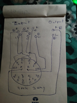
Ok. Just did a crude drawing. I have used a 4 pole switch of which only two poles have been used
1688323065243.png
 
Last edited:
Is it possible to build an INPUT selector with ON-OFF-ON toggle switch ?

View attachment 73417

The need is,
I have an amplifier which only takes one audio input (left and right).
I want to connect two inputs to it (using above switch) , So that I can either choose the first input or second input.

I am not able to figure out how the wiring would be.

This might have worked well
 
What is confusing above is that there are 4 relays and only 3 pairs of RCA sockets. The colours are for Component video. Better clarify with gtech audio. I will provide the wiring diagram later as I will have to draw it and take a photo and I'm feeling lazy right now. But will do it tomorrow if no one else responds. Maybe I will open my selector box and show the wiring.
Here is another one from audiocrafts

Ok. Just did a crude drawing. I have used a 4 pole switch of which only two poles have been used
View attachment 78102
This is what I also use in my passive preamplifier. It's 2 pole-5way selector switch.

I use to have a 5 way relay based switch with miniature Japanese relays, but I felt the associated diodes, and coil can affect the low-level input and went the passive switch method.
 
Last edited:
I need it for stereo amplifier. I would still appreciate if you can post the wiring diagram for mono.
I have another one of same type, so may be I can use that to wire other channel, so two knobs (one for left channel and other for right) to turn if I have to switch input.
As mentioned, 1 switch each for mono & stereo is too cumbersome.

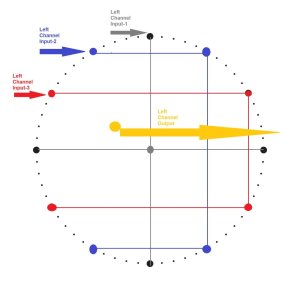
However, since you gave asked for a schematic... Given Below (for 1 channel) using yr existing switch.

Each of yr 3 inputs are shown in 3 different col;ours: Grey, Blue & red.

The Channel output is in yellow.

Switch.jpg
 
What is confusing above is that there are 4 relays and only 3 pairs of RCA sockets. The colours are for Component video. Better clarify with gtech audio. I will provide the wiring diagram later as I will have to draw it and take a photo and I'm feeling lazy right now. But will do it tomorrow if no one else responds. Maybe I will open my selector box and show the wiring.
Here is another one from audiocrafts

Ok. Just did a crude drawing. I have used a 4 pole switch of which only two poles have been used
View attachment 78102

I got the switch.
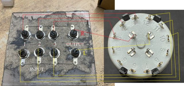
Are you able to please review below diagram?
Its the ground I am bit confused.
Where should ground from RCA be going?
Shouldn't ground be going to switch as well?

panel-back.jpg
 
I got the switch.
Are you able to please review below diagram?
Its the ground I am bit confused.
Where should ground from RCA be going?
Shouldn't ground be going to switch as well?

View attachment 78227

Good work done by you in understanding the switch. Kudos

Mostly ground is common to both left and right channels. So you don't have to do anything other than connecting the ground using a single straight bare copper wire and solder it across all 8 terminals.

You have two spare poles. One of them can be used to light up LED indicator for each input.
Thank you :)

Led for selected input? Does that mean, the switch also need separate power?
Just so that you know, this thing I am building stays as a separate unit 2 feet away from amplifier.
 
Thank you :)

Led for selected input? Does that mean, the switch also need separate power?
Just so that you know, this thing I am building stays as a separate unit 2 feet away from amplifier.
forget the led thing I said. Why complicate it? Yes it will require power for the led if you want to do that. Bringing a wire with power near the switch will also introduce noise. Forget that I ever told you to light up the led :p
 
I wired and tested.
Every thing works.
Small minor issue I found is, 3rd input's right audio is slightly bleeding over 1st input right audio (when 1st input is selected, and 3rd input audio is playing in background). I think this is a known issue?

To make sure its not selector issue, I used multimeter and checked for continuity between
1st - left output and right input and made sure that no beeps when non selected ones are touched
2nd - right output and right input and made sure that no beeps when non selected ones are touched
Any multimeter which uses DC for testing continuity will never show the leakage. This leakage will always happen. The three wires going from the switch selector become like a capacitor with each other. A capacitor will always allow non-dc current to pass through. Further the distance between the wires, lesser will be the leakage. Inside the switch too, the terminals are close to each other and there will be minor leakage happening there too. The capacitance formed between the wires and terminals will be picofarads
 
Get the Wharfedale EVO 4.2 3-Way Standmount Speakers at a Special Offer Price.
Back
Top