You are using an out of date browser. It may not display this or other websites correctly.
You should upgrade or use an alternative browser.
You should upgrade or use an alternative browser.
Finally my DIY tube amp project gets kick-started
- Thread starter Hari Iyer
- Start date

Yes, thanks for suggesting. I was thinking of the same and also a CVT as an option. Need to decide this later after building if the voltage issues are not getting resolved.A high quality servo stabilizer may work very well or a online double conversion ups . This would take up space and do produce fan noise.
I would suggest avoiding the cvt. Online double conversion UPS from a reputed brand is one of the best.Rock solid clean output.Infact you can set the output voltage in ups to 200,220,230V ac etc .Yes, thanks for suggesting. I was thinking of the same and also a CVT as an option. Need to decide this later after building if the voltage issues are not getting resolved.
Ok, thanks for suggesting. Any brand that you can suggest? I am a noob at this.I would suggest avoiding the cvt. Online double conversion UPS from a reputed brand is one of the best.Rock solid clean output.Infact you can set the output voltage in ups to 200,220,230V ac etc .
Option 1 (w/o backup) :Servo Stab : I guess you are in Mumbai ?There are few good ones in Mumbai,Pune for sure. Krykard and Vertex are from Chennai . I am using Vertex .Vertex can also offer with OBO Bettermann India Private Limited surge filters at extra cost.Ok, thanks for suggesting. Any brand that you can suggest? I am a noob at this.
Option 2 : UPS : online double conversion :APC SMART-UPS RC 1000VA 230V INDIA Harsh Environment / SRC1KI-IN (has indian sockets)
This works for me as i have used it in a area that has brownouts/blackouts/low voltage/phase failures but has some quirks.
Fan is noisy when battery charges .The beep has to be manually muted when main power fails.
Eaton is also ok but the output sockets are IEC type !
Option 3 : Best : Servo followed by online double conversion UPS
Option 4 : Many folks already may have existing PC UPS and pure sine wave invertor .In this case use a servo stab followed by ups or invertor . This needs two boxes and messy in small space situation.
***** Note : Avoid as much as possible ups/invertor for load cold starting ie when no mains is present avoid switching on the load *****
Last edited:
I am unable to attach any build images as the size is too large to upload. Btw, yesterday I received all pending materials and assembled the unit which is still WIP. I could check the B+ voltages with using 2 incandescent lamps (15 watts each) as resistive load. As per my math they should draw around 60mA of current. This gave me a B+ of 545v DC with an line AC input of 247v which is kind of OK. With lower input voltage there will be further drop in B+. Also my continuous RMS current is around 85mA. So am holding all thoughts of buying any line input voltage regulators currently.
Resize the images in paint and then uploadI am unable to attach any build images as the size is too large to upload.
Past two days I was working on various option to tame the input AC voltage without much increasing the source impedance and at the same time not having much impact on the transient response. I researched many option that included an online UPS, CVT, Servo stabilizer, step down transformers and Variacs. Each has its pros and associated cons. Finally narrowed upon using a bucking transformer as they were best suited for dropping small line voltages which in my case was around 15v to 20v AC. Since I had many unused transformers lying around in different corners of the home, I thought of making one quickly to test the concept. Since was not having one transformer suitable for my voltage drop, I wired two of them in series to achieve the required voltage drop. So the two transformers were 230v/12v @ 4 A sec current and 230v/8.2v @ 12A sec current .
After connecting them, I measured 252v AC input and 231v AC output and got around 21v voltage drop. Ironically the bucking Transformer need not be rated similar to the main load transformer as they don't draw too much current. For a 2KVA load the primary current required is around 950mA. I am not too sure how much they would heat up once a load is connected, but this I will need to check and confirm. But the concept worked for me in principle.
Thanks for looking.
PS: will the bucking Transformer in any way help in avoiding inrush current? There is an added DCR of around 100 ohms due to this transformer now and if it helps then I am even more happy. The turnon surge will be absorbed by the buckers sparing the main tube transformer with inrush.
Last edited:
There is a channel called jsb electric on YouTube , https://m.youtube.com/channel/UCmLMWpbfKHMX5lRfzf2qYgw , who teaches youngsters to wind Transformers and make stabilizers from scratch. Maybe you could contact him and have one made as per your requirements for input and output voltage rangeGood option, again the question of increasing the impedance of the power supply line and space to keep the stabilizer. I am not sure if the stabilizer work to keep the voltage always to 230v or if they operate only beyond 250v. Will need to discover this.
Thanks for suggesting, but the issue is I don't have any control on the AC input voltage coming from the grid. Most application needs a correction either manual or automatic. I erred by having only a single 230v tap in the transformer primary. Given the current voltage scenario at Thane, it will be wise to have atleast 4 primary tappings as 220v, 230v, 240v and 250v and have a voltage selector switch at the backside. But again you will need to know line voltages at all times to use the switches appropriately. Again a +/- 10volts variation from 230v is ok even for tubes, but the life of the tubes are drastically reduced. I am trying to be as precise as possible to reduce the aging effect.There is a channel called jsb electric on YouTube , https://m.youtube.com/channel/UCmLMWpbfKHMX5lRfzf2qYgw , who teaches youngsters to wind Transformers and make stabilizers from scratch. Maybe you could contact him and have one made as per your requirements for input and output voltage range
If you watch his videos on how to make a stabilizer you will find that he makes what you are looking for. He has many videos on various input voltages, as many taps and relays with one output voltage that you can use as source voltage for your units transformer.Thanks for suggesting, but the issue is I don't have any control on the AC input voltage coming from the grid. Most application needs a correction either manual or automatic. I erred by having only a single 230v tap in the transformer primary. Given the current voltage scenario at Thane, it will be wise to have atleast 4 primary tappings as 220v, 230v, 240v and 250v and have a voltage selector switch at the backside. But again you will need to know line voltages at all times to use the switches appropriately. Again a +/- 10volts variation from 230v is ok even for tubes, but the life of the tubes are drastically reduced. I am trying to be as precise as possible to reduce the aging effect.
Since he explains right from scratch how to calculate the winding, size of core, wire etc for the transformer as well as how to connect the relays, I'm very sure that you could simply design and make one that's simpler and better quality than commercial offerings.
No harm searching his list and checking out a few videos. Some models that he had demonstrated are from 90v to 300v. They are all automatic and you don't need to manually select input voltage
Where as for you in Thane the voltage range won't be that wide, you could simply make as many input taps in a narrow range that you've measured and make a smaller transformer and tighter control
There are two otherchannels, diodegonewild and the post apocalyptic inventor, that could be of interest to you. I think both have made variac based isolation transformers of you want to adjust it manually
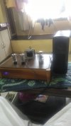
As suggested by FM @sadik i have resized images in paint and posting my amplifier build progress for benefit of DIY FMs,


 h
h
This top plate is currently temporary and will be replaced by brass once i have the final softone audio output transformer after 6 months


Connected 2, 15 watts incandescent bulb in series as load to test the B+ voltage. With 245V AC could measure a B+ of 545 volts. Designed B+ is for 505v. The 15 watts bulb would draw around 60mA of current.


Thanks for looking.
hThis top plate is currently temporary and will be replaced by brass once i have the final softone audio output transformer after 6 months
Connected 2, 15 watts incandescent bulb in series as load to test the B+ voltage. With 245V AC could measure a B+ of 545 volts. Designed B+ is for 505v. The 15 watts bulb would draw around 60mA of current.
Thanks for looking.

Completed the built yesterday late evening and gave them a spin. Used my microTL speaker as load for testing. They sang and now have completed around 3 to 4 hours of break-in. Yet to connect my main OB speakers and give them a listen. Shall plan later in the evening.
Attachments
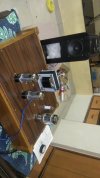
DIY builders - check that the driver tube is behind and closer to the. RCA input with just a 4" silver plated copper cable. It does not have to cross anything and reduce any noise pickup. Don't try to build a good looking amplifier, use your discretion in the layout.
If you notice closely the rectifier tubes are spaced in a golden ratio and they are far away from the power and driver tubes in the front side. Also they are far away from the power transformer. If you notice inside the hood all transformers and choke are on the left side and all the amplifier section are on the right side. The driver and power tubes are again in GR distance from each other and both the rectifier, driver and final tubes are GR from the chassis inner edge. The chassis internal itself is a golden ratio.
The outcome of this is no hum whatsoever in the amplifier that use only 300mH x2 of choke and just 30uF + 50uF of total power supply capacitor. This makes the amplifier fast and they play music.
Attachments
Hi Hari, congrats on completing your monoblok amplifier. Can’t wait to hear your impressions when the other is completed.
You’ve allied yourself I beleive with one of the best free thinkers as it pertains to this type of amp topology. I had a very similar experience as you did this past year when I reached out to Jeff Medwin wanting to build a pair of #45 monoblocks, this after acquiring most parts for build I decided against 45’s after speaking with Jeff. Long story Short, I have a 6b4g set which he very dilligently & kindly advised me on upgrades and could not be happier with.
My plan was to build this dc coupled kt88 amp this year but unfortunately I’ve had some family set backs etc. however I do plan on building asap. Enjoy & I look forward to further listening impressions.
Have fun!
Hi Susnick, I have borrowed all advise from Jeff in this built as this is the first time I am building a tube amp. Yesterday he advised me to cut all the cable ties because he felt the wires radiate and should not be tied together. Tieing wires are more for good looks rather than any sonic benefits as per Jeff. With the tie residual AC noise measured 11+mVAC and after removing the tie it was just 6.03mVAC.. This confirms Jeff's observations too.Hi Hari, congrats on completing your monoblok amplifier. Can’t wait to hear your impressions when the other is completed.
You’ve allied yourself I beleive with one of the best free thinkers as it pertains to this type of amp topology. I had a very similar experience as you did this past year when I reached out to Jeff Medwin wanting to build a pair of #45 monoblocks, this after acquiring most parts for build I decided against 45’s after speaking with Jeff. Long story Short, I have a 6b4g set which he very dilligently & kindly advised me on upgrades and could not be happier with.
My plan was to build this dc coupled kt88 amp this year but unfortunately I’ve had some family set backs etc. however I do plan on building asap. Enjoy & I look forward to further listening impressions.
Have fun!
And about the Hum in his LSES power supply that get trolled in so many forums - it's all fake and they try to demean him without any reason. If it was true why is my amplifier not having any hum? It's not that my amp is having the greatest layout, but it's too over exaggerated out of proportion.
Last edited:
Wharfedale Linton Heritage Speakers in Walnut finish at a Special Offer Price. BUY now before the price increase.
Similar threads
- Replies
- 27
- Views
- 1K