
The current lockdown period allowed me to utilize the time to measure the loudspeaker more with less ambient noise outside my home. I wanted to experiment with time-alignment between mid-woofer and tweeter and spent most of the time reading technical articles about them. Also tried electrical time delay using RC network to delay the high frequency by frew msec. Also did a physical off-set of mounting the tweeter from behind and again checking the step response for integration and after experimenting for 10+ days with measurement and listening, finally will be settling with the sloping baffle method.
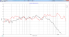
The tweeter offset gives serious diffraction issues which can only be tamed (not avoided) by the absorbing surfaces. The flat baffle made the tweeter sound much brighter than they should, but the sloping bafffle (around 18mm) gave me the right balance between the mids and highs. Here are some FR and step measurements,


If you notice step-1 and step-3 just by tilting the baffle, the tweeter energy is reduced significantly without much affecting the frequency response. This can be a useful tool for someone who finds their setup a little more airy or bright just by raking the front baffle by few mm. How much to rake can be tuned by listening too and would not require a measurement imo.
The tweeter offset gives serious diffraction issues which can only be tamed (not avoided) by the absorbing surfaces. The flat baffle made the tweeter sound much brighter than they should, but the sloping bafffle (around 18mm) gave me the right balance between the mids and highs. Here are some FR and step measurements,
If you notice step-1 and step-3 just by tilting the baffle, the tweeter energy is reduced significantly without much affecting the frequency response. This can be a useful tool for someone who finds their setup a little more airy or bright just by raking the front baffle by few mm. How much to rake can be tuned by listening too and would not require a measurement imo.


") -
-