Help!!! - Practical difficulty with Decoupling Capacitor on Single Channel op-amps

mbhangui

Well-Known Member
Joined
Jun 25, 2011
Messages
2,157
Points
113
Location
Pune
I have constructed a dual op-amp using two LME 49990. Now only the V+ and V- comes to the pins of the chip. None of the pins have ground. This is the case even for traditional dual op-amp like OPA 2134. However decoupling is easier for a dual channel op-amp as the op amp will be soldered on the main board itself and it wouldn't be too difficult to provide placement for decoupling caps on the board itself.

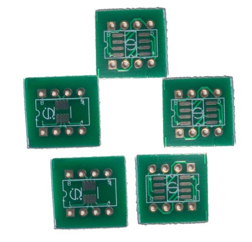
Now for constructing a dual op-amp from single channel op-amp like 49990, I have used a separate PCB with LME 49990 soldered on the top and bottom. I have replaced the original op-amp with this board. However, I think there is some oscillation as the chips are running hot. Since there is no ground, what is the technique for connecting two decouping 100 nf caps (v+ to ground and v- to ground)?
 
Re: Help!!! - Practical difficulty with Decoupling Capacitor on Single Channel op-amp

If there is place on the main board for the two decoupling caps to ground, install it there itself. Alternatively, install them on the daughter-board with a wire from their center-point (ground) to the power ground star-connection point.

The main board already has decoupling caps. Installed a 100nf across v+ and v- (pin 4 and pin 6) on the daughter board). This has caused a constant hiss and all songs with s becomes sssss :eek:hyeah:

Next is to solder two caps across pins 4 and 6 and take a ground wire to the joint legs on the caps. Not sure how that will help with a long wire going from the star ground to the cap joint. And it will look ugly.

Time being, run with hot lme 49990. The best sound I have got till now compared to whole lot of other dual op-amps.
 
Last edited:
Re: Help!!! - Practical difficulty with Decoupling Capacitor on Single Channel op-amp

I think I made a mistake. The cap should have been across pin 4 and 8 instead of pin 4 & 6
 
Re: Help!!! - Practical difficulty with Decoupling Capacitor on Single Channel op-amp

This is a single opamp. Supply pins are 4 (-V) and 7 (+V) ! Output is pin 6.
 
Re: Help!!! - Practical difficulty with Decoupling Capacitor on Single Channel op-amp

@Fantansic: mbhangui is using 2 x soic opamps into 8 pin dual opamp DIP packages adapter. So pin 4 & 8 are correct on adapter.
 
Re: Help!!! - Practical difficulty with Decoupling Capacitor on Single Channel op-amp

@Fantansic: mbhangui is using 2 x soic opamps into 8 pin dual opamp DIP packages adapter. So pin 4 & 8 are correct on adapter.

Yes, Omishra, you are right about the DIP package adapter. It was too late yesterday to try the caps on pin 4 & 8. Will try it today.

The sound emanating from Rod Elliot's Pre-amp using LME 49990 is fantastic. I will try today and see if it solves the heating problem. BTW, the heat is not too much without the caps, as I am able to touch the chip. The earlier op-amp OPA 2134 did not even get warm.

I also came across this what someone else has done. Just solder one cap on the power rail on the top. (post #1670)

http://www.head-fi.org/t/432749/the-opamp-thread/1665
 
Last edited:
Re: Help!!! - Practical difficulty with Decoupling Capacitor on Single Channel op-amp

problem about IC LME49990 is that it has BW of 110MHz :D
So for audio band, keeping oscillation under control is tough job. That unheard frequencies heat up that OPAMP IC. I am also using it with solder one 10uF cap on top with pin 4&8 with correct polarity.
 
Re: Help!!! - Practical difficulty with Decoupling Capacitor on Single Channel op-amp

I am also using it with solder one 10uF cap on top with pin 4&8 with correct polarity.

Are you using a 10 uF tantalum capacitor?
 
Re: Help!!! - Practical difficulty with Decoupling Capacitor on Single Channel op-amp

no its electrolytic + .01F (marked at 10nF or 103) paralleled. Looks ugly but does the job.
 
Re: Help!!! - Practical difficulty with Decoupling Capacitor on Single Channel op-amp

Just got an idea, to avoid the work looking ugly. I have plenty of these single SOIC to DIP 8 adapter. Will solder two thick tracks (using legs of a large capacitor). One connecting 1, 2,3 and 4 and another connecting 5, 6, 7 & 8. This will create a parallel power supply rail. Solder two caps (one smd and one electrolytic), either across or perpendicular on the SOIC tracks. Have only two thick legs (one on pin 4 and one on pin 8) and solder the two thick legs on this board over the pin 4 & 8 of the dual dip adapter. Do you think this will work?

51vcHAiUqCL.jpg
 
Last edited:
Re: Help!!! - Practical difficulty with Decoupling Capacitor on Single Channel op-amp

Component legs are soft and adapter pins are hard like needle. So careful while making choice. You may get loose contact and don't sacrifice in quest of visual pleasure which no one is looking at it.
 
Re: Help!!! - Practical difficulty with Decoupling Capacitor on Single Channel op-amp

problem about IC LME49990 is that it has BW of 110MHz :D
So for audio band, keeping oscillation under control is tough job. That unheard frequencies heat up that OPAMP IC. I am also using it with solder one 10uF cap on top with pin 4&8 with correct polarity.
maybe ferritebeads may help to tame down the RF noises :eek:
i cooked a pre with RF capable mOsfets and used FBs as per desiigners instructions


nice read for fixing instability in highspeed op-amps Proper Design Techniques Solve High-Speed Op-Amp Stability Problems | Analog content from Electronic Design
 
A beautiful, well-constructed speaker with class-leading soundstage, imaging and bass that is fast, deep, and precise.
Back
Top