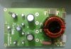
One of my area of expertise due to my profession is designing high speed RF PCBs with sometimes upto 6-Layers, which includes power planes, ground planes and signal layers. These PCB's are sometimes used in high speed data communication such as DACs ,Class-D amplifiers upto 10KW and state of the art analog gear which has resolution to hundreds of kilohertz.

My reasoning about Right Angled Tracks was not due to any difficulty in manufacturing such pcbs or materials non-availability.
You are wrong in saying that right angled tracks have no considerable effect until the frequency is in GHZ range, because in numerous experiments which i have conducted for example the rise and fall times of a 20khz square wave shows a considerable difference + ringing while using your right angled tracks and same effect was eliminated when octagonal bends were used. Secondly when making a high performance analog gear one always like to extend the upper range bandwidth to 100khz often which simply points to the direction that one must have adequate slewrate which again demands less ringing and fast rise and fall times for best transient response ever.
Hum is a result of power supply ripple current entering sensitive nodes in circuitry. You can have groundplanes and still can have hum. That is not the case. The main idea behind the ground plane is to keep the common mode currents confined to small area, providing RF shielding [Ingress from outer noisy environment] , keeping the power supply ripple current conduction loop minimum.
A groundplane acts as a groundplane till its one and single throughout the pcb[The first and basic rule of groundplane as per physics], not like in yours which has been hacked to death by power supply rails going to Opamps. This is a pseudo groundplane.
")
Yes your ceramics are CLOSE to supply pins, but do they share same common mode path for returning ripple currents for ground, certainly no. Try thinking why.
. Also there is no differential filtering of rails, its missing.
Yes the design works and enjoyed by many, i said this in my previous post also.

AD797 is a high speed opamp requires a high speed layout to complement the performance.
You obviously have much more experience with PCB designs than I do and most others, kudos to you for that.
As you say the design works so the problems are purely incidental to the listener.
The ceramics work according to my scope, the data sheet and Rod Elliot's advice is, as he said the critical thing is the connection to the power pins is as close as possible, the connection to ground is secondary, he seems to have a common sense approach to this.
")
This is designed to run on batteries.
So let's sum up:
1. The noise is low, way lower than the surface noise of the record.
2. There is no hum.
3. The op amps don't oscillate, I have tested them with my scope.
4. The signal is unadulterated I checked with my signal generator and scope and it's clean and free of distortion.
5. It's the best sounding phono stage I have heard and easily beats out stages costing ten times what it costs to build.
Which begs the question why do commercial designs perform poorly when they are designed by the so called experts?
I mean no offense and I appreciate your input but everything doesn't have to be turned into a science project.
Going by your definition, the AD797 is an integrated circuit which has more than 10 transistors on the chip through which the signal passes and if we compare this with a normal 3 JFET phono stage, you tell me which one is complex and which one is simpler.

hyeah:
Time for you to get surprised.....

The noise of 2SK170[0.95nV/Hz@1k] and AD797[0.9nV/Hz@1k] is comparable as per single units are concerned.
So the noise of one 2SK170 is comparable to the 10 transistor chip of the AD797?
It's the onboard resistors and capacitors that degrade the sound most IMO, YMMV.
You will see there are very few in my design.
No need to beat your chest and come back with a long and detailed reason why I am wrong, I believe you, but you really should build this to see how well it works.
And maybe you can try what you suggest to see how much improvement it makes.
I think this phono stage is so polarizing, because it performs way above what it should and does go against some hackneyed views on design.
Before people get to carried away and this turns into a pissing contest let me give you some background on how this project got started, I was wanting a simple to build, well performing, with few easy to obtain components, MC phono stage.
It would also have adjustable impedance and gain on the fly, and run on batteries.
I was using a customized CA640P with discreet front end, then the Phonoclone 3, then my own design of the clone, each one was better than the last.
When this was built and tweaked a little it easily outperformed these other stages.
So if you want a great bang for your buck stage that will embarrass stages costing huge sums this may be for you.
Paralleled pairs of matching 2sk170 or 2sk370 transistors may in fact give lower noise and be a better way to go, but the spirit of this design is ease of build, availability of parts and low parts count.
I also built some Leach designed MC head amps with paralleled matched transistors and did not like the sound, which is another reason I steered towards the AD797 being a low noise, good sounding yet sometimes cranky op amp. Also the second stage op amp LME49990 is a winner in this spot, many were tried but it sounds the best overall, thank you Sachin for putting me onto it.
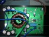
If Kanwar would like to post some pictures of changes to the PCB layout I would welcome them and could incorporate them in my next build.
But lets not have a pissing contest.