Ita from banggood. I ll share more details of it.Can you share a link from where you have got this picture?
A Circuit or any additional details are worth a thousand words
This seems to use Op Amps for the tone controls (which need LOTS of gain) and probably a tube buffer.... a Good start even though I'm not really into tone controls... If your system can resolve and present musical detail... a tone control is not required (IMO) to exaggerate the details "In Your Face".
You are using an out of date browser. It may not display this or other websites correctly.
You should upgrade or use an alternative browser.
You should upgrade or use an alternative browser.
JLH1969 Class A amplifier build
- Thread starter ashar
- Start date
Can you share a link from where you have got this picture?
A Circuit or any additional details are worth a thousand words
This seems to use Op Amps for the tone controls (which need LOTS of gain) and probably a tube buffer.... a Good start even though I'm not really into tone controls... If your system can resolve and present musical detail... a tone control is not required (IMO) to exaggerate the details "In Your Face".
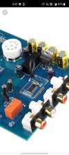
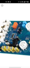
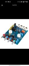
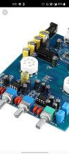
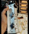
1.Original 6J5 tube, original NE5532Can you share a link from where you have got this picture?
A Circuit or any additional details are worth a thousand words
This seems to use Op Amps for the tone controls (which need LOTS of gain) and probably a tube buffer.... a Good start even though I'm not really into tone controls... If your system can resolve and present musical detail... a tone control is not required (IMO) to exaggerate the details "In Your Face".
2.The main filter capacitor uses the original 470UF/25V, and the coupling capacitor uses the imported capacitor 1UF.
3.The resistor uses a high-precision chip resistor to ensure a good signal-to-noise ratio.
4.PCB uses 1.6mm thick double-sided sheet, 2.0 oz copper thickness, spray tin full process, to ensure good passing performance of large and small current. First-class PCB quality.
5.Input and output with gold-plated RCA seat, durable and beautiful!
6.The board layout is reasonable, beautiful, and the current is small.
Basic parameters:
Power supply: DC12 V2A (DC)
Size: length 133* width 89* height 22MM (without tube height)
Here are the screenshots from banggood
Attachments
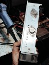
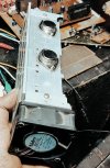
Although the the earlier heatsink is getting loads of love from forum members,i just wanted to try the original pioneer heatsink aswell so i got another set of transistors and mounted it will do some tests to see if this holds good as i need more space for other modules,preamps and caps. it runs a 24v fan for induced cooling .
Attachments
IndianEars
Well-Known Member
Thanks, but besides Point 1. stated by you there is little to make a judgement call.1.Original 6J5 tube, original NE5532
2.The main filter capacitor uses the original 470UF/25V, and the coupling capacitor uses the imported capacitor 1UF.
3.The resistor uses a high-precision chip resistor to ensure a good signal-to-noise ratio.
4.PCB uses 1.6mm thick double-sided sheet, 2.0 oz copper thickness, spray tin full process, to ensure good passing performance of large and small current. First-class PCB quality.
5.Input and output with gold-plated RCA seat, durable and beautiful!
6.The board layout is reasonable, beautiful, and the current is small.
Basic parameters:
Power supply: DC12 V2A (DC)
Size: length 133* width 89* height 22MM (without tube height)
A circuit diagram and price are essential to take an informed decision.
If price is low you can take a punt.... Do note that it probably does not include the Power Supply, including a High Voltage for the Tube anode....
Its cheap at 1500 rs + shipping. Runs on 12v dc .Thanks, but besides Point 1. stated by you there is little to make a judgement call.
A circuit diagram and price are essential to take an informed decision.
If price is low you can take a punt.... Do note that it probably does not include the Power Supply, including a High Voltage for the Tube anode....
The power supply should be 12v 2a dc.Thanks, but besides Point 1. stated by you there is little to make a judgement call.
A circuit diagram and price are essential to take an informed decision.
If price is low you can take a punt.... Do note that it probably does not include the Power Supply, including a High Voltage for the Tube anode....
It has built in step up boost converter for the tubes.
But i read we can improve the design by separately powering the tubes.
You may find Muse in diyaudiocart and ELNA in theaudiocrafts.Its beautiful, any source for output capacitor , the ones m using were the best i could find.
IndianEars
Well-Known Member
Yes, the built in anode voltage booster will be a switching supply with lots of switching noise. An external supply for the tubes will certainly help.
However the built in voltage booster for the valves will give you an idea if the sound quality is to yr liking to begin with, and whether you should spend more in improving it.
Rs 1500 is a cheap enough punt !")
However the built in voltage booster for the valves will give you an idea if the sound quality is to yr liking to begin with, and whether you should spend more in improving it.
Rs 1500 is a cheap enough punt !
HormusPeston
Active Member
A great build. Congratulations. I built three 1996 JLH amps and all are working fine today, twenty years later.
If memory serves, the quiescent current Iq depended primarily on the gain of the output transistor which changed when the transistor got hot. A 'good-enough' value was achieved using a lookup table of Vpk and Zout. Stick to these values. Rodd Elliot's site has a nice overview on the JLH. Geoff Moss had also compiled a cheat-sheet which is excellent.
If Iq is, say 2.5A, on 22V rails, then the amp will pour around 10W into an 8ohm speaker, and the rest (around 40W) into the heatsink, per channel. The fan in your design will help! I hope it isn't too noisy. Again, the heatsink and fan arrangement should be such that the transistor's temperature remains stable. My JLH had a massive finned heatsink -- about 40cm long, 10cm wide and deep -- for each channel. I don't remember the measured Iq but it was enough to keep those heatsinks comfortably warm.
A happy DIY memory on Valentine's Day: My young neighbours liked to share their music sessions with me (and everyone else in our PIN code), which is a nice gesture even though we have very different tastes in music... I have passionately hated all the lovesick Boyz (Backstreet, Mainstreet etc.,) and the lovelorn Girls (Spice, non-spice, green-haired, hairless, etc.) and their music system gave literal meaning to the song "Hello from the other side." Anyway, the young couple came over one evening to see the audio system of "the engineer uncle next door". I'd moved on to a simple LM chip-amp in the mid 2000s and then to headphones last year, but I dusted off the JLH and the 6" Fostex rear-loaded horns for them to audition. They loved the sound! I gave the JLH to them; also gave them the horns, an sx-amp (also a great class-A design), a turntable, a CD-player, and three cartons of LPs. They love LPs for some strange reason. I'd digitised my CDs to 320kbps mp3 files and I cannot tell the difference so I gave them all my CDs as well. What matters is that everyone is happy! The wife bosses around an Alexa connected to a Bose system in the living room; I'm in my study with my headphones, and the JLH is QUIETLY warming the hearts (and house) of the kids next door.
Therefore, I submit that low-power DIY Class A amps contribute to world peace and love among neighbours, and for that reason I am happy to ignore their impact on global warming. (A dear friend of mine has built a Zen room-heater that is capable of putting out 60W of Class-A audio power, but he and I will be dead long before it affects us -- the kids next door, though, might have to deal with it.)
Congratulations on your build and I wish you many happy years with your JLH.
Cheers,
~hp
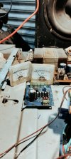
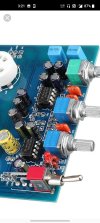
Fever 6j1 preamp and passive tone control.
I ll be using the 6j1 preamp , but it has no tone control so a passive control will sit between the pre and power. Need inputs on this if this the correct topology. Or if there r better passive tone control that should not modify the sound coming from the bile tubes.
I ll be using the 6j1 preamp , but it has no tone control so a passive control will sit between the pre and power. Need inputs on this if this the correct topology. Or if there r better passive tone control that should not modify the sound coming from the bile tubes.
Attachments


amrutmhatre90
Well-Known Member
@ashar your build is turning out to be very good. Waiting for end result.
Will the power amp and pre amp be separate?
If not just a suggestion, if possible keep them separate. You can mix match and try having different pre amps built yourself or try the ones which are already available too. Since power amplifier will be built, you won't have to open the whole thing and rework on it.
Leaving the power amp alone Makes complete sense. Thanx for the input. What i plan is to add a direct in for power amp and have a permanent tube pre amp which can be switched to external pre or internal.@ashar your build is turning out to be very good. Waiting for end result.
Will the power amp and pre amp be separate?
If not just a suggestion, if possible keep them separate. You can mix match and try having different pre amps built yourself or try the ones which are already available too. Since power amplifier will be built, you won't have to open the whole thing and rework on it.
i am also got the same DiyAudioCart PCB, not assembled hence please suggest the R1 and R2 values, also DYC Bill of Materials recomm the input cap. value of .47 - 1.5 uF, which one i take?Just stumbled upon this build, great going and very interesting heatsink. JLH is a very capable amp and can drive most of the speakers with ease even without a pre.
If I may, some suggestions,
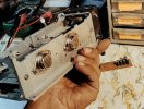
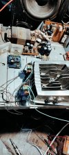
I had completed mine recently and it is my primary amp currently. Sharing some pics of the build, not to hijack your thread but it might give you some ideas.
- Change the decoupling cap at the speaker out to any good audio grade cap, these has direct impact on the sound and clearly audible. Choose Nichicon Muse, ELNA Gold or similar for this application.
- Change the board positions to either side of the heatsink and keep the transistor wire length to minimum, longer wire can cause oscillations and even hum with higher biasing.
- Increase the biasing of transistor, that will change the character of an amp. Basically you need to change the R1 and R2 values.
(Ashar take 1uF for his JLH project). Also please guide me for construction & Power supply...
Your JLH looks like worldclass one. If u PM me i will send my no . Thanks in advance Guru...
A small Intro...
I was fooled by some of so called Audiophiles, hence I jump into the DIY field but does have any knowledge in this field, my capability is to soldering and identify the components some what . consider this for your suggestions. once again Thanks Chetta ...
IndianEars
Well-Known Member
A larger / large enough heat sink will also keep temperatures low. This is the Best (Only?) solution for this design (see below).One quick question for experts , will parallel pair of transistors help reduce heat generated by each just to prolong the life of transistors and have lesser effect on quinscient current after transistors heat up.
While 2 parallel transistors will share the heat dissipation and, there are other factors to consider, some of which include:
1. Two Parallel transistors will present a larger (too large in this case) load for the Bootstrapped Driver to handle. Distortion and transient response will suffer.
2. The 2 Paralleled Transistors (in any design) will have atleast slightly different characteristics, including static parameters like hfe (current Gain), internal emitter Resistance, as well as dynamic characteristics such as transient response.
There is one school of thought that phoo phoos multiple, paralled output devices, as the 2 paralleed devices could be "fighting each other" when in use. Individual emitter resistors for each output device help reduce "current hogging" but do not resolve the difference in dynamic characteristics between multiple output devices.
Ofcourse, there are a large number of commercial designs that use multiple., paralleled devices out of sheer necicity, but their Driver stage must be designed accordingly. Even after that, a certain level of performance compromise remains inherent.
The JLH Class A audio amp follows the KISS principle
(Keep It Simple, Stupid) ... so I would recommend a larger heatsink 
Sir, Is transistor matching compulsory for JLH???A larger / large enough heat sink will also keep temperatures low. This is the Best (Only?) solution for this design (see below).
While 2 parallel transistors will share the heat dissipation and, there are other factors to consider, some of which include:
1. Two Parallel transistors will present a larger (too large in this case) load for the Bootstrapped Driver to handle. Distortion and transient response will suffer.
2. The 2 Paralleled Transistors (in any design) will have atleast slightly different characteristics, including static parameters like hfe (current Gain), internal emitter Resistance, as well as dynamic characteristics such as transient response.
There is one school of thought that phoo phoos multiple, paralled output devices, as the 2 paralleed devices could be "fighting each other" when in use. Individual emitter resistors for each output device help reduce "current hogging" but do not resolve the difference in dynamic characteristics between multiple output devices.
Ofcourse, there are a large number of commercial designs that use multiple., paralleled devices out of sheer necicity, but their Driver stage must be designed accordingly. Even after that, a certain level of performance compromise remains inherent.
The JLH Class A audio amp follows the KISS principle
IndianEars
Well-Known Member
It is not "Compulsory" though best results (lowest distortion) are obtained with Output Transistors of approximately equal current gain (hfe).Sir, Is transistor matching compulsory for
If the gains of the output transistor are unequal, the Output Transistor with the higher current Gain should be used as TR-1.
Do note that no catastrophic failure4 will result even if you use Output Transistors with significantly different Hfe.... Only distortion will be slightly higher.
There is a Good Site devoted to this amplifier & circuit, including the original article (attached) in the April 1969 issue of Wireless World.
The original article also discusses in detail, the use & effects of un-matched output transistors.
I have used 2N3055 devices as the output transistors, without any matching, and the results were sonically very good to my ears
Attachments
Thanks GuruIt is not "Compulsory" though best results (lowest distortion) are obtained with Output Transistors of approximately equal current gain (hfe).
If the gains of the output transistor are unequal, the Output Transistor with the higher current Gain should be used as TR-1.
Do note that no catastrophic failure4 will result even if you use Output Transistors with significantly different Hfe.... Only distortion will be slightly higher.
There is a Good Site devoted to this amplifier & circuit, including the original article (attached) in the April 1969 issue of Wireless World.
The original article also discusses in detail, the use & effects of un-matched output transistors.
I have used 2N3055 devices as the output transistors, without any matching, and the results were sonically very good to my ears

Join WhatsApp Channel to get HiFiMART.com Offers & Deals delivered to your smartphone!
Similar threads
- Replies
- 24
- Views
- 10K
- Replies
- 0
- Views
- 240