Hello folks,
This is my fun, getting hands dirty DIY LM3886 amplifier. It was started during lockdown, as I had nothing to do. But later got busy so finished it when time permitted. I have no knowledge of proper electronics so cant answer technical questions. But ask me other things. As some of you know I just build to listen to the sound and move on. So this amplifier will be on sale soon to fund my next DIY project. The amp works perfectly and sounds good. LM3886 is probably last class AB high quality IC. Specifications are great for 40 watts in to 8 ohms. My main goal was to build as cheap as possible and had budget of 5K which exceeded . But it is built with love.
Some details...
This LM3886 chinese module and most parts are from GTech audio (Tamil Nadu). Some parts they couriered by air which was not necessary. Overall good experience with Gtech Audio. Smaller chassis was chosen to save money so amp is little bit congested inside. And I misjudged speaker terminal space from modules. But it is manageable. There are details after some picture and cost of the project, which probably will be helpful to new diyers like me. Audio CD will give you some perspective.


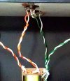
(1) Power on light and wire routing aluminum clips. (2) Extension shaft from robotics project (3) Mains Terminal to fuses and transformer from AC mains. There is plastic film below PS boards. (4) 1.5A fuse for each channel. Earlier I had two pole on/off switch but it broke so am using single pole switch for live wire. Separate fuse on two PS board. There is also an extra third main fuse.

(5) Capacitor from Input ground to chassis to attenuate RF (6) Grommet from CD player mechanism (mains in has turntable grommet (7) PS 0v two wires and mains earth wire grounded to Amplifier main chassis (8) Four 4700uf Caps. per channel. Silly me I thought caps would get hot so removed original sleeves then put on new one realizing the outer capacitor case will be carrying voltages.

(Top Left) Power on light made from LED TV backlight bulb plastic. (Top Right) 10 K volume pot made fake logarithmic with a resistor. (Bottom Left) Speaker Terminals. (Bottom Right) Aluminum piece is on IC just for countersunk hole for screw.
Approximate build cost.

")
Thanks for watching. Suggestions welcome and will be highly appreciated.
Regards
This is my fun, getting hands dirty DIY LM3886 amplifier. It was started during lockdown, as I had nothing to do. But later got busy so finished it when time permitted. I have no knowledge of proper electronics so cant answer technical questions. But ask me other things. As some of you know I just build to listen to the sound and move on. So this amplifier will be on sale soon to fund my next DIY project. The amp works perfectly and sounds good. LM3886 is probably last class AB high quality IC. Specifications are great for 40 watts in to 8 ohms. My main goal was to build as cheap as possible and had budget of 5K which exceeded
. But it is built with love.Some details...
This LM3886 chinese module and most parts are from GTech audio (Tamil Nadu). Some parts they couriered by air which was not necessary. Overall good experience with Gtech Audio. Smaller chassis was chosen to save money so amp is little bit congested inside. And I misjudged speaker terminal space from modules. But it is manageable. There are details after some picture and cost of the project, which probably will be helpful to new diyers like me. Audio CD will give you some perspective.
(1) Power on light and wire routing aluminum clips. (2) Extension shaft from robotics project (3) Mains Terminal to fuses and transformer from AC mains. There is plastic film below PS boards. (4) 1.5A fuse for each channel. Earlier I had two pole on/off switch but it broke so am using single pole switch for live wire. Separate fuse on two PS board. There is also an extra third main fuse.
(5) Capacitor from Input ground to chassis to attenuate RF (6) Grommet from CD player mechanism (mains in has turntable grommet (7) PS 0v two wires and mains earth wire grounded to Amplifier main chassis (8) Four 4700uf Caps. per channel. Silly me I thought caps would get hot so removed original sleeves then put on new one realizing the outer capacitor case will be carrying voltages.
(Top Left) Power on light made from LED TV backlight bulb plastic. (Top Right) 10 K volume pot made fake logarithmic with a resistor. (Bottom Left) Speaker Terminals. (Bottom Right) Aluminum piece is on IC just for countersunk hole for screw.
Approximate build cost.
Thanks for watching. Suggestions welcome and will be highly appreciated.
Regards
Last edited: