My Cute AMPCAMP Built

This is strange but in DIY these things do happen :)

Few quick hints:

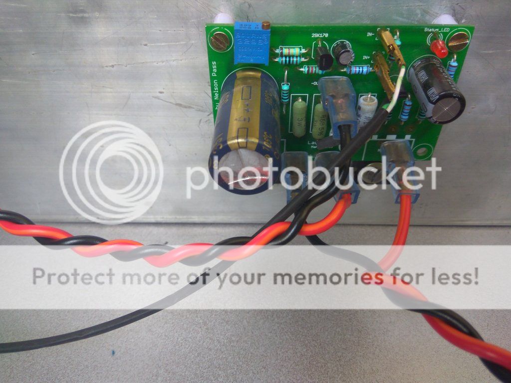
1. check the components values and their placements with schematic and their orientation, esp. transistors (Q3, ztx450 near blue cap).
2. check for dry solder joints
3. post pics of the other side of the pcb, there might be soldering bridges etc
4. build one board and test it, mimic it for 2nd board

Checked the components, Solder joints.
Have to check for any soldered bridges. Will do that. Will post the pics as well.

2nd board already soldered, but didn't check yet.
 
Re: My Cute AMPCAMP Build started

Just check input ground and live are correctly connected. It may be everything is correct. Just connection issue.
 
Finally worked, problem was loose solder in positive lead of power capacitor (the large one). It seems proper solder but actually not. Now amp singing nice.

Thanks Balu, because of you started to check again on all solders not visual but with multimeter.

One more doubt, is the pin position of Bourns variable resister is fixed or any position is OK?
 
Good to hear that the amp singing.. enjoy..

I soldered the Bourns slanting i.e. parallel to pcb by bending its leads. I think it should not matter as once the bias is setup you wont be touching it again :)

If you align the trimmer screw with that of pcb marking there is no second way of soldering it i guess..;)
 
Last edited:
Good to hear that the amp singing.. enjoy..

I soldered the Bourns slanting i.e. parallel to pcb by bending its leads. I think it should not matter as once the bias is setup you wont be touching it again :)

If you align the trimmer screw with that of pcb marking there is no second way of soldering it i guess..;)

I didnt mean the orientation, I am asking like a normal resistor can the pins be soldered vice versa ( 1-2-3 or 3-2-1)?

First time I soldered like the pin inline with adjustable screw on the other side of 3 pins (other side of the screw mark in the PCB) , but still the Q1 voltage was showing 10V.

PS: Just getting the basics of variable resistor
 
yes, it doesnt matter in situations like this where pot is used for bias, it does make a difference in terms of how the pot behaves when you rotate it clockwise/anti clockwise. eg., usual experience is volume increase when you rotate clockwise (cw), decrease when you rotate counter-clockwise (ccw). If you swap pins 1 and 3, this behaviour reverses.
 
Re: My Cute AMPCAMP Build started

Are you using two power supplies? If yes then you need two switches. If no then divide output wire from switch, into two for separate amp boards.
 
Re: My Cute AMPCAMP Build started

Are you using two power supplies? If yes then you need two switches. If no then divide output wire from switch, into two for separate amp boards.


Yes Mishra, 2 laptop adapters. Can I connect one normal switch with 2 terminals (like dptp switch) connecting each negatives or separate switches are better?
 
Re: My Cute AMPCAMP Build started

Yes Mishra, 2 laptop adapters. Can I connect one normal switch with 2 terminals (like dptp switch) connecting each negatives or separate switches are better?

if you have access to DPDT switch then job done. That will switch the two +ve poles of both power supplies with single point operation. but do soldering carefully, use heatshrink tubing cover after soldering switch wires.

I thought you have only SPDT as shown in link. No need of two switches.
 
Just finished reading the whole thread. Pretty much exited to build one. Already sent email to sachin for kit availability. Keeping my fingers crossed. :)

Awesome built by everyone. However, I am not able to view pics posted by Raghu (post #1, #17) :sad:

A quick question to veterans. Have anyone tried ACA with K-Buffer? If yes, how did it perform?
 
Finally I was able to put the ACA in a Case. you know what was the most difficult part in my builds getting a cheap case for the amps, There are a lot of options if you can spend alot of money.

I wanted to keep the cosmetic investments less then the stuff inside the amp. (doesn't want to waste money on the things which doesn't make any sound improvement.

I have done the 6 watt mod and want some advise on the heating of a 5w resistor which is shown in the 3rd Pic, 2nd resistor from the left, this resistor reaches around 48C may be sometimes 50C, is this fine or should I revert the 6W mod.

I have also measured the temp on the heatsink just behind the Mosfet's it is around 41-42C.

before the 6 watt Mod the temperature was moderate, as the heatsinks are huge.

The mosfet's/heatsinks and the 2nd resistor stay hot, while playing as well as Idle, is this normal?

Please advise

Below are the Images

16-07-15-17-19-37-679_photo_zpszzx2pmul.jpg


16-07-15-17-21-57-287_photo_zpsth2acz7z.jpg


16-07-15-17-24-13-954_photo_zpsvhhnkilr.jpg


16-07-15-17-23-18-785_photo_zpsyr9olbrz.jpg


16-07-15-17-21-26-228_photo_zpss72xrkh0.jpg
 
Re: My Cute AMPCAMP Build started

Both green resistances are parallel to each other. Must be sharing current. Please verify on other board too. Otherwise check soldering of colder ones.

Congratulations, nice build.
 
Re: My Cute AMPCAMP Build started

Thanks for the quick reply, this resistance heating is common on both the channels, I ran the amp for more than 2 hours but nothing burnt yet. Is this fine. The resistance temperature doesn't increase beyond 50c, I'm do not know what is operational temperature it can handle.

Btw: the amp sings nicely better than the 5w (without mod), and it sounds effortless even at full volume.

Sent from my Redmi Note 3 using Tapatalk
 
Re: My Cute AMPCAMP Build started

If both the green resistances in same board are heating equal then it's okay, no problem.
Regards
 
Re: My Cute AMPCAMP Build started

I think these good quality resistance will not be available locally, and I don't want to use comprised quality resistance in that place hence I will keep it as it is and enjoy the music, If I see any serious issues then i will think about replacing it.

Hope nothing goes wrong with it, I don't want to revert the 6w mod for obvious reasons (increase in power and lower distortion).

Regards
Bilal

Sent from my Redmi Note 3 using Tapatalk
 
Re: My Cute AMPCAMP Build started

Just measure Voltage across both green resistances. If it is equal then leave it. No problem.
 
Re: My Cute AMPCAMP Build started

Yes, the voltage is equal on both resistance and both channels, it is around 10-11v.

Regards
Bilal

Sent from my Redmi Note 3 using Tapatalk
 
Re: My Cute AMPCAMP Build started

Amp looks stable as of now even though the resistance heating, sound quality is excellent, no hum no hiss at all and has amazing vocals (at least for my non-golden ears).

Thank you omishra sir for the help, you are always helpful and reachable.

Regards
Bilal

Sent from my Redmi Note 3 using Tapatalk
 
A beautiful, well-constructed speaker with class-leading soundstage, imaging and bass that is fast, deep, and precise.
Back
Top