You are using an out of date browser. It may not display this or other websites correctly.
You should upgrade or use an alternative browser.
You should upgrade or use an alternative browser.
My PCB layout & PCB for Jean Hiraga 30 Watt Class A Amplifier
- Thread starter sadik
- Start date

Today's Update:
Today I Completed the kit and testing was done. At first start it did not go well, I really got depressed, only the True DIY'ers who built right from developing PCB board to assembly can understand this feeling of depression...(the thoughts in mind, like let it be a small problem....kaash yeh mehanet doobara na karni pade) sorry for those Hindi words.
Then made a quick check & found i had reversed the polarity of 47uf Cap & told myself let this be the alone problem other then wrong tracks.. So I quickly change the Polarity & the pcb was on the test bench again & this time it was Success.
On testing i found the Green LED flicker rate was too fast, so i searched again in diyaudio forum & found the solution (i changed the 470 Ohms resistor to 2.7K & increased the value of Capacitors from 2.2uf to 10uf) now the flicker rate was visible. With addition to this I also found the DC cut off Voltage rating for this PCB, It was about 9 Volts. 9VDC in my opinion will be too Big Value for Home Use so reading further i found the Resistor values which Operates the Relays at 3VDC and i thought this value will be good for setting the DC voltage. (here i changed the 27k resistors to 18k)
Now after above modifications i did a quick DC test by using the Motor Speed Controller, there is POT, which on rotating increases the DC Voltage. At about 2.5 to 2.8 V the Relays were steady, at 3 volts to 4.5 volts the relays operated (but took about a half sec or so, above 4.5 VDC i think the relays operated within or close to 10 to 15 milli sec, I Dont have an Idea about acceptable time limit within which the realys should operate.
Below is the Photo of PCB Powered on:

Regards,
Sadik
Today I Completed the kit and testing was done. At first start it did not go well, I really got depressed, only the True DIY'ers who built right from developing PCB board to assembly can understand this feeling of depression...(the thoughts in mind, like let it be a small problem....kaash yeh mehanet doobara na karni pade) sorry for those Hindi words.
Then made a quick check & found i had reversed the polarity of 47uf Cap & told myself let this be the alone problem other then wrong tracks.. So I quickly change the Polarity & the pcb was on the test bench again & this time it was Success.
On testing i found the Green LED flicker rate was too fast, so i searched again in diyaudio forum & found the solution (i changed the 470 Ohms resistor to 2.7K & increased the value of Capacitors from 2.2uf to 10uf) now the flicker rate was visible. With addition to this I also found the DC cut off Voltage rating for this PCB, It was about 9 Volts. 9VDC in my opinion will be too Big Value for Home Use so reading further i found the Resistor values which Operates the Relays at 3VDC and i thought this value will be good for setting the DC voltage. (here i changed the 27k resistors to 18k)
Now after above modifications i did a quick DC test by using the Motor Speed Controller, there is POT, which on rotating increases the DC Voltage. At about 2.5 to 2.8 V the Relays were steady, at 3 volts to 4.5 volts the relays operated (but took about a half sec or so, above 4.5 VDC i think the relays operated within or close to 10 to 15 milli sec, I Dont have an Idea about acceptable time limit within which the realys should operate.
Below is the Photo of PCB Powered on:
Regards,
Sadik
Sadik I salute you........ what an effort really a diy beauty
Those words mean a lot to me .... Thank a lot my friend....
Re: My PCB layout & PCB for Jean Hiraga 30 Watt Class A Amplifier
You must be feeling more than happy while listening to your setup. Isn't it?
One suggestion,
In relay rating, there is switch on voltage and little less keep on voltage. So you can add little resistance and capacitor which starts relay at little high voltage quickly. Then capacitor discharge below switch on voltage and kept at lower sustainable on voltage.
Great effort, [emoji122]Today's Update:
Today I Completed the kit and testing was done. At first start it did not go well, I really got depressed, only the True DIY'ers who built right from developing PCB board to assembly can understand this feeling of depression...(the thoughts in mind, like let it be a small problem....kaash yeh mehanet doobara na karni pade) sorry for those Hindi words.
Then made a quick check & found i had reversed the polarity of 47uf Cap & told myself let this be the alone problem other then wrong tracks.. So I quickly change the Polarity & the pcb was on the test bench again & this time it was Success.
On testing i found the Green LED flicker rate was too fast, so i searched again in diyaudio forum & found the solution (i changed the 470 Ohms resistor to 2.7K & increased the value of Capacitors from 2.2uf to 10uf) now the flicker rate was visible. With addition to this I also found the DC cut off Voltage rating for this PCB, It was about 9 Volts. 9VDC in my opinion will be too Big Value for Home Use so reading further i found the Resistor values which Operates the Relays at 3VDC and i thought this value will be good for setting the DC voltage. (here i changed the 27k resistors to 18k)
Now after above modifications i did a quick DC test by using the Motor Speed Controller, there is POT, which on rotating increases the DC Voltage. At about 2.5 to 2.8 V the Relays were steady, at 3 volts to 4.5 volts the relays operated (but took about a half sec or so, above 4.5 VDC i think the relays operated within or close to 10 to 15 milli sec, I Dont have an Idea about acceptable time limit within which the realys should operate.
Below is the Photo of PCB Powered on:
Regards,
Sadik
You must be feeling more than happy while listening to your setup. Isn't it?
One suggestion,
In relay rating, there is switch on voltage and little less keep on voltage. So you can add little resistance and capacitor which starts relay at little high voltage quickly. Then capacitor discharge below switch on voltage and kept at lower sustainable on voltage.
Last edited:
Hello Mishra Ji.
Suggestions are always welcomed, but for me i cannot understand by reading because i have not studied electronics. Yes but i can understand if you can point out in schematic where should i change the things and what should be its value.
I will be thankful to you if you can download the schematic from the below link and edit it and send it back to me, it will be easy for me to understand.
https://drive.google.com/open?id=0B2a9DN9GbmtBLU80Q25CaHprdVE
I am sending you my e mail address in your PM.
Regards
Sadik
Re: My PCB layout & PCB for Jean Hiraga 30 Watt Class A Amplifier
Sadik, I got it. I will see tomorrow. Do you have coil resistance value for your relay. I will try to download data sheet if any. We need those operating voltage range of relay and coil resistance.
Sadik, I got it. I will see tomorrow. Do you have coil resistance value for your relay. I will try to download data sheet if any. We need those operating voltage range of relay and coil resistance.
Re: My PCB layout & PCB for Jean Hiraga 30 Watt Class A Amplifier
I Checked the resistance it is around 380 to 382 Ohms. The operating voltage for each relay is 12V. Both relays are fitted in Series so that total Operating voltage must be 24 Volts. The transformer i am using has 0-20Vac secondary.
Sadik, I got it. I will see tomorrow. Do you have coil resistance value for your relay. I will try to download data sheet if any. We need those operating voltage range of relay and coil resistance.
I Checked the resistance it is around 380 to 382 Ohms. The operating voltage for each relay is 12V. Both relays are fitted in Series so that total Operating voltage must be 24 Volts. The transformer i am using has 0-20Vac secondary.
Hi Friends,
After a very long time there are some updates on my Jean Hiraga 30 Watt Class A Amp.
In my earlier posts you all may have seen that I have had already completed the PCB & The Project was pending due to shortage of funds for Power Supply and Heat Sink. I did saved some bucks for Heat sink, I was searching for some suitable heat sink which shall also be able to make side walls for the Enclosure of this Amp. But i did not get the desired length of heat sink, hence i had to settle down on N9 Model of heat sink from Perfect Metal Works, Bangalore.
I will be using heat sink of size 205 x 82 x 120 (H) I have ordered 4 Nos of Heat Sinks, I will be Joining 2 Nos heat sinks with each other to make side wall of Enclosure, Below you can see the Pic, this Pic is just for an reference, It may change according to actual conditions which i will have to face during assembly.


Now the height of Enclosure will be 120 mm & Depth will be 410 mm (It will be sufficient for this Amp) width will be decided later on.
Now the Question arises how to mount the PCB on these heat sinks, because of the Size of PCB, The size is small & Both the transistors are placed very close to each other. If I use this PCB then heat will not be distributed equally on Both Heat Sinks, hence there will be problem regarding heat dissipation. To over come this issue I redesigned the layout of this PCB. The size of new PCB is 200 mm x 70 mm. I Placed the output transistor away from each other so as one can be mounted on Each Heat Sink & Heat will be evenly distributed on Both Heat sinks (Bahut Mehenat karni padi doston ). Secondly in this new layout I made provisions to use the original transistors as well as equivalent transistor. Below is the layout of same.

Below are the Images of Completed & Tested PCB. The PCB will be Mounted same way as on this Testing Heat Sink.


Sadik
After a very long time there are some updates on my Jean Hiraga 30 Watt Class A Amp.
In my earlier posts you all may have seen that I have had already completed the PCB & The Project was pending due to shortage of funds for Power Supply and Heat Sink. I did saved some bucks for Heat sink, I was searching for some suitable heat sink which shall also be able to make side walls for the Enclosure of this Amp. But i did not get the desired length of heat sink, hence i had to settle down on N9 Model of heat sink from Perfect Metal Works, Bangalore.
I will be using heat sink of size 205 x 82 x 120 (H) I have ordered 4 Nos of Heat Sinks, I will be Joining 2 Nos heat sinks with each other to make side wall of Enclosure, Below you can see the Pic, this Pic is just for an reference, It may change according to actual conditions which i will have to face during assembly.
Now the height of Enclosure will be 120 mm & Depth will be 410 mm (It will be sufficient for this Amp) width will be decided later on.
Now the Question arises how to mount the PCB on these heat sinks, because of the Size of PCB, The size is small & Both the transistors are placed very close to each other. If I use this PCB then heat will not be distributed equally on Both Heat Sinks, hence there will be problem regarding heat dissipation. To over come this issue I redesigned the layout of this PCB. The size of new PCB is 200 mm x 70 mm. I Placed the output transistor away from each other so as one can be mounted on Each Heat Sink & Heat will be evenly distributed on Both Heat sinks (Bahut Mehenat karni padi doston
). Secondly in this new layout I made provisions to use the original transistors as well as equivalent transistor. Below is the layout of same.
Below are the Images of Completed & Tested PCB. The PCB will be Mounted same way as on this Testing Heat Sink.
Sadik
You've spread the transistors sufficiently wide to be able to use the two heatsinks.
If you want to ensure thermal equilibrium between the two halves of the heat sink, you could use a thick copper bus bar to join the two sinks. MOSFETs to be mounted on the bus bars, per usual. The bus bar must span the full length of the two heat sinks to allow more contact surface between copper bus bar to aluminium heat sinks. Use lots and lots of nut-bolts to join bus bar to heat sinks. I think using heat sink compound at the jointed surface will improve the heat transfer. If I remember correctly, that's what we did for magma's F5T cabinet.
If you want to ensure thermal equilibrium between the two halves of the heat sink, you could use a thick copper bus bar to join the two sinks. MOSFETs to be mounted on the bus bars, per usual. The bus bar must span the full length of the two heat sinks to allow more contact surface between copper bus bar to aluminium heat sinks. Use lots and lots of nut-bolts to join bus bar to heat sinks. I think using heat sink compound at the jointed surface will improve the heat transfer. If I remember correctly, that's what we did for magma's F5T cabinet.
You've spread the transistors sufficiently wide to be able to use the two heatsinks.
If you want to ensure thermal equilibrium between the two halves of the heat sink, you could use a thick copper bus bar to join the two sinks. MOSFETs to be mounted on the bus bars, per usual. The bus bar must span the full length of the two heat sinks to allow more contact surface between copper bus bar to aluminium heat sinks. Use lots and lots of nut-bolts to join bus bar to heat sinks. I think using heat sink compound at the jointed surface will improve the heat transfer. If I remember correctly, that's what we did for magma's F5T cabinet.
Thanks for your suggestion Bro, But i really don't see any need of Bus Bar, as I will be mounting Each Transistor on Single Heat Sink.
Yes copper plate of 5mm thickness and 4-6" wide will be okay. Also invest into artic silver like heatsink compound between heatsink and copper. 6-8 number of M5 bolts will sufficient for each piece of heatsink to copper joint. So total 12-16 at each channel. No compound will also do.
may be rubber HS coupling is better way .
I have heard the HIrega 30watt is overhyped . But always will be worth the money
Kept the parts for it and got trafo done a year ago .. waiting for DIY bug to bite me
I have heard the HIrega 30watt is overhyped . But always will be worth the money
Kept the parts for it and got trafo done a year ago .. waiting for DIY bug to bite me
Re: My PCB layout & PCB for Jean Hiraga 30 Watt Class A Amplifier
Are you pointing silicon heat pads as rubber? If so then they are highly inefficient here. Direct metal contact is always better. Still no to welding. But due to small air gaps, better to use high quality thin layer of thermal grease or compound.
Are you pointing silicon heat pads as rubber? If so then they are highly inefficient here. Direct metal contact is always better. Still no to welding. But due to small air gaps, better to use high quality thin layer of thermal grease or compound.
Re: My PCB layout & PCB for Jean Hiraga 30 Watt Class A Amplifier
somewhere i have heard that the transistors of the class A have to be insulated from HS.. poor memory") if that is so silicon(yes!) washers is one choice
if that is so silicon(yes!) washers is one choice
Are you pointing silicon heat pads as rubber? If so then they are highly inefficient here. Direct metal contact is always better. Still no to welding. But due to small air gaps, better to use high quality thin layer of thermal grease or compound.
somewhere i have heard that the transistors of the class A have to be insulated from HS.. poor memory
if that is so silicon(yes!) washers is one choiceRe: My PCB layout & PCB for Jean Hiraga 30 Watt Class A Amplifier
For large heatsink I'm not sure which pad.
Even I used sil-pad under devices of F5t v2 amplifier. But it's good quality but not kerotherm(if I remember correctly).somewhere i have heard that the transistors of the class A have to be insulated from HS.. poor memory
For large heatsink I'm not sure which pad.
Some more updates on my built.
Recently got the Heat Sinks & Toroidal. The heat sinks were pruchased from Perfect Metal Works Bangalore, The size is 205mm (W) x 120 mm (H) & fin Height is about 80 to 82 mm (Model N9) Total quantity 4 Nos. The cutting job was not so good, it was not in right angle, Secondly the surface at which the Transistor was to be Mount was not even. Below is the Pic of Heat Sink.


I had to do machining job to make the cutting side it in right angle posistion as well as make an even surface for transistor mounting. The final size for which i had to settle down was the height of 117 mm.


& Below is the Pic of Toroidal Transformer this was purchased from Torotrans (Pune) rating is 25-0-25 (250Va) I had ordered 2 Nos because i will be making Dual Mono.

Now for the PSU, I have finalized to used Capacitance multiplier from Elliott Sound Products, each for Single channel. I have used 2SC5200 & 2SA1943 transistors instead of TIP, for 470uf I have used 1000uf Capacitor & for 10000uf i have used 15000uf Capacitor.

In original Hiraga Amp the Capacitor bank is about 1.2Farads. So I would like to have suggestions from Forum members on this. What will be the difference in sound quality or Performance of this amplifier by using Capacitance Multiplier.
Sadik
Recently got the Heat Sinks & Toroidal. The heat sinks were pruchased from Perfect Metal Works Bangalore, The size is 205mm (W) x 120 mm (H) & fin Height is about 80 to 82 mm (Model N9) Total quantity 4 Nos. The cutting job was not so good, it was not in right angle, Secondly the surface at which the Transistor was to be Mount was not even. Below is the Pic of Heat Sink.
I had to do machining job to make the cutting side it in right angle posistion as well as make an even surface for transistor mounting. The final size for which i had to settle down was the height of 117 mm.
& Below is the Pic of Toroidal Transformer this was purchased from Torotrans (Pune) rating is 25-0-25 (250Va) I had ordered 2 Nos because i will be making Dual Mono.
Now for the PSU, I have finalized to used Capacitance multiplier from Elliott Sound Products, each for Single channel. I have used 2SC5200 & 2SA1943 transistors instead of TIP, for 470uf I have used 1000uf Capacitor & for 10000uf i have used 15000uf Capacitor.
In original Hiraga Amp the Capacitor bank is about 1.2Farads. So I would like to have suggestions from Forum members on this. What will be the difference in sound quality or Performance of this amplifier by using Capacitance Multiplier.
Sadik
I feel you don't machine corners of your heat sinks. Join them by copper bars, that looks enough to me. Just remember to spread drivers on each heatsink equaly.
You can see, there are groves on the edge of the heatsink. They are there for some purpose. You can use square lock nut inserted into that groove and tighten anything using bolts. Take one heatsink on hardware shop for buying proper locking nuts. IMO rigid 10mm Aluminum face place to 3mm back plate, anything could be attached safely and securely.
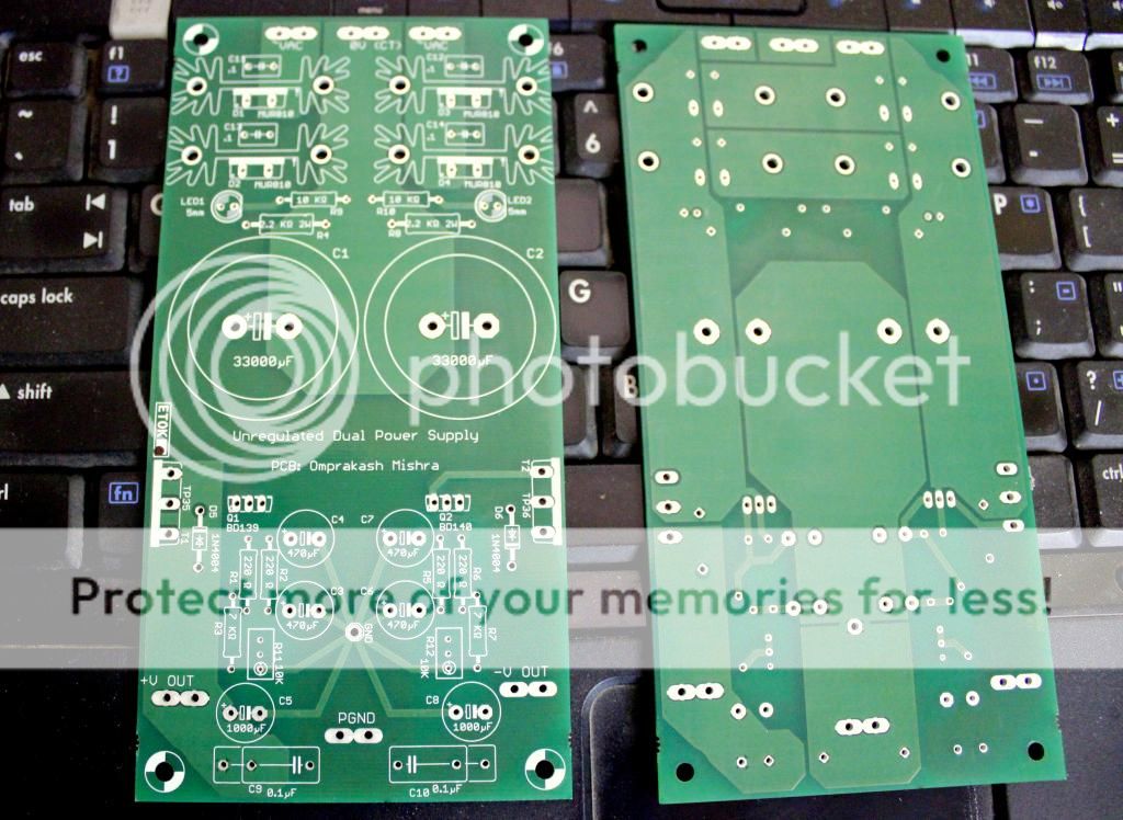
That rod elliot capacitance multiplier - I have made one PCB and we used it into our Jean Hiraga build with success. I made few tweaks to it for fine tuning output voltages because tolerances of components add difference into output rails. I broken that 12K resistance into 7K + 5K, 5K is middle position of 10K present. So you can go on either side. Also charging ground current of big capacitor is separated from discharging line. You can also see star grounding.
Also see there is bleeder of 3.3K 1W added, must be there as we have used large capacitance of 33000uF.
You can see, there are groves on the edge of the heatsink. They are there for some purpose. You can use square lock nut inserted into that groove and tighten anything using bolts. Take one heatsink on hardware shop for buying proper locking nuts. IMO rigid 10mm Aluminum face place to 3mm back plate, anything could be attached safely and securely.
That rod elliot capacitance multiplier - I have made one PCB and we used it into our Jean Hiraga build with success. I made few tweaks to it for fine tuning output voltages because tolerances of components add difference into output rails. I broken that 12K resistance into 7K + 5K, 5K is middle position of 10K present. So you can go on either side. Also charging ground current of big capacitor is separated from discharging line. You can also see star grounding.
Also see there is bleeder of 3.3K 1W added, must be there as we have used large capacitance of 33000uF.
Last edited:
Purchase the NEW Audiolab 6000A MkII Integrated Amplifier at a special offer price.