Simple IR Remote for Motorized Alps Pot directly using Arduino.

KiranPS

Well-Known Member
Joined
May 13, 2012
Messages
151
Points
63
Location
Chennai
When I wanted to control the Motorized ALPS pot for my PASS B1, I started
doing research and found that most MCUs used a H-Bridge using PNP+NPN transistors or HBridge ICs to drive the motor bidirectionally.

Then by chance I came across this article in elektor.
http://dr-shost.com/files/article.pdf

Here elektor guys have used a MCU IO Pins to drive the motor directly. Their calculation is that One ATMega IO Pin is capable of sourcing or sinking 20ma so you can connect 6 IO pins in parallel to source or sink 120ma. Since the ALPS motor requires only 100 ma for movement this should be more than sufficient. We also don't run the motor continuously, we run it only in 50ms steps.

I followed this idea and was able to drive my ALPS pot without any external components.
I have used A0-A5 ports of the arduino for one terminal of the motor and Pins 2-7 for the
other, now from the program its just a matter of setting one set of Pins to High and other
to Low to move the motor either-way. I have not included any end detection circuits /code since this pot has a slip clutch which does not damage the motor when it reaches either end.

For IR Remote I have used the library from

https://github.com/shirriff/Arduino-IRremote

I have attached the sketch.

The Sketch also prints the type of the remote and the keycode received.
For customizing to your remote, press the keys and notedown the keycode printed in the Arduino IDE serial console. Next you can just change the values in the if command in the loop() function to match the keys noted.

There are extra 4 IOs left (8,9,10,11) These can be used to switch the input
on the input selector board.

Sketch : http://g-box.in//Downloads/Private/gArduinoRemote.zip
 

Attachments

  • 20130525_173130.jpg
    20130525_173130.jpg
    23.5 KB · Views: 539
  • 20130525_173331.jpg
    20130525_173331.jpg
    17.9 KB · Views: 536
  • Arduino.jpg
    Arduino.jpg
    20.4 KB · Views: 544
Nice.
Even i am doing something like this,only i have not been able to source a motorized pot,so,now i am trying to make it work with a cirrus 3310 digital pot.
So,where did you buy it from?
To prototype,i tried it out with a cd-rom mechanism motor,using the same driving methods and i find that my the regulator got very hot.finally,it gave up.I had the arduino uno smd edition.
I did implement the selector mechanism too.

I am using a small car audio system remote,have to find a good universal remote for this though.

Another thing would be,instead of the leds showing the input selected,a implementation like the AMB LCDuino would be a perfect solution,showing the channel,volume etc.
 
Thanks really helped, First Project and I forgot to buy a H-Bridge but you have saved the effort. Thanks! :D
 
Ravi,

Thanks so much for this thread. I am brand new to arduino but I wanted to make as much of my amp on my own. So much more "fun" than buying ready to use remotes and receivers.

I changed my code around to suit my experimenting, and it is based of the Mega2560 which has more mA per I/O pin. Please check the data sheets on your gear first.

The reason I am posting is that I added a bit because my remote sends repeat signals when you hold down the button. So using this code, you can have the volume pot rotate smoothly, or bump it a little at a time.

I hope this helps someone out.


/* This was a learning sketch to incorporate a bourns motorized pot (Mouser 652-PRM162K415K104A2 )for tube amp input volume control making use of a repeating code when holding
down remote button. The motor draws 100mA max so I have allotted 3 pins for each of the leads, giving 120 mA on the Mega 2560 board. I am using pin 22 at random for the IR input. Otherwise wiring is same as KiranPS's photo. I have an arduino brand IR sensor 38 Khz on this project.

*/


#include <IRremote.h>
#include <IRremoteInt.h> // This library does not need to be included at this point but it seems like it might be important?
long oldValue; // This value will save the last meaningful remote input and reuse it in the case of a repeat
int RECV_PIN = 22; // The pin that recieves the IR sensor Output. The leftmost pin when looking at the eye with pins down.
int volDelay = 175; //this value can be changed to move volume for longer increments

IRrecv irrecv(RECV_PIN); // The core IR parts of the program and the libraries come from Ken Shirriff's blog: A Multi-Protocol Infrared Remote Library for the Arduino
decode_results results;


void MotorOff()
{
digitalWrite(48,LOW); // The core code for motor control came from http://www.hifivision.com/diy/44275-simple-ir-remote-motorized-alps-pot-directly-using-arduino.html
digitalWrite(49,LOW); // this sets the functions for each mode of motor movement
digitalWrite(50,LOW);

digitalWrite(51,LOW);
digitalWrite(52,LOW);
digitalWrite(53,LOW);
}

void MotorUp()
{
digitalWrite(48,HIGH);
digitalWrite(49,HIGH);
digitalWrite(50,HIGH);

digitalWrite(51,LOW);
digitalWrite(52,LOW);
digitalWrite(53,LOW);
}


void MotorDown()
{
digitalWrite(48,LOW);
digitalWrite(49,LOW);
digitalWrite(50,LOW);

digitalWrite(51,HIGH);
digitalWrite(52,HIGH);
digitalWrite(53,HIGH);
}

void setup()
{
pinMode(48,OUTPUT);
pinMode(49,OUTPUT); //setting power to motor pins for 5v output
pinMode(50,OUTPUT);

pinMode(51,OUTPUT);
pinMode(52,OUTPUT);
pinMode(53,OUTPUT);

MotorOff();
Serial.begin(9600);
irrecv.enableIRIn(); // Start the receiver
}


void loop()
{
if (irrecv.decode(&results))
{
Serial.print(results.bits, DEC);
Serial.print(" --results.value"); //printing newly recieved IR code to serial monitor
Serial.print(results.value, HEX);
irrecv.resume(); // Receive the next IR code. This code is an interrupt, so the arduino can go on with other tasks.

if (results.value==0x807FD02F) //if up button pushed move motor forward with a 250ms shot of 5V
{
oldValue=results.value; //setting the placeholders value
MotorUp();
delay(volDelay); //this value can be changed to move volume in bigger increments
MotorOff();
}

else if (results.value==0x807FE01F) // down button pushed
{
oldValue =results.value;
MotorDown();
delay(volDelay);
MotorOff();
}
else if (results.value==0xFFFFFFFF) // button is held down, do the last thing done, again
{
if (oldValue==0x807FD02F)
{
MotorUp();
delay(volDelay);
MotorOff();
}

else if (oldValue==0x807FE01F)
{
MotorDown();
delay(volDelay);
MotorOff();
}
}


Serial.print(" --oldValue");
Serial.println(oldValue, HEX); // this shows the placeholder at work and starts a new line in the serial monitor

}
}


Cheers,
Luke
 
Thanks very much Kiran for your post.:clapping: I have tried your method and it works fine. I am using it for my sub (SubZero by Dr.Bora).

I have used the other pins for

1. Soft start
2. Speaker protector - borrowed from Rod Elliott
3. Temperature sensor and fan switch > 60deg and shutdown > 70deg
4. Power on button

I have timed the power on delay so that it switches on last after the power amp

I have used an Atmega328 chip with arduino bootloader from Mouser $4.95, transplanted it into the arduino uno and uploaded the sketch.

I have used TSOP4838 for the IR sensor and a Samsung TV remote. DS1882 x 2 for sensing temperature in both heatsinks. courtesy arduino.cc

I will post the PCB lay out and the sketch for above functions next post.
The motorized Alps pot RK168 / RK27 is available from theaudiocrafts , Delhi for INR 600/- (< $10)

The entire PCB is the size of the Arduino Uno. The whole non-audio components costing < $30.

And the only original contribution from me is the PCB design :eek:
 
you can do away with 100rs bare bones ARduino :) I will post later how to .
DAC voltage to the lightspeed photo attenuator is another way to achive quality
volume on remote .

A nice looking LCD will be cool
dsc03359.jpg
 
Last edited:
Hi Friends
I have attached the PCB layout in Express PCB and arduino sketch for the circuit to:
1. Control Alps pot
2. Switch on fan at set temp and disconnect speaker if too hot
3. Speaker protect
4. Soft start with delay
5. Mains Filter
6. IR receiver with barebones arduino
for my Sub amp by Dr.Bora

Hope somebody finds it useful

#include <IRremote.h>
#include <OneWire.h>
#include <DallasTemperature.h>
#define ONE_WIRE_BUS 3
OneWire oneWire(ONE_WIRE_BUS);
DallasTemperature sensors(&oneWire);
DeviceAddress L_temp = { 0x22, 0xFB, 0x10, 0x2C, 0x00, 0x00, 0x00, 0x01 };
DeviceAddress R_temp = { 0x22, 0x74, 0x19, 0x2C, 0x00, 0x00, 0x00, 0x3C };
long oldValue; // This value will save the last meaningful remote input and reuse it in the case of a repeat

int RECV_PIN = 2; // The pin that recieves the IR sensor Output. The leftmost pin when looking at the eye with pins down.
int volDelay = 175; //this value can be changed to move volume for longer increments

IRrecv irrecv(RECV_PIN); // The core IR parts of the program and the libraries come from Ken Shirriff's blog: A Multi-Protocol Infrared Remote Library for the Arduino
decode_results results;

const int PWR_RLY = 4;
const int FAN_RLY = 5;
const int SPK_RLY = 6;
const int SPK_IN = 8;
const int PWR_BUTTON = 7;
const int LED = A0;

int tempC = 0;
int LTemp = 0;
int RTemp = 0;

int SPK_VAL = 0;
int PWR_VAL = 0;
int PWR_OLDVAL = 0;
int PWR_STATE = 0;

void setup() {
pinMode(A0,OUTPUT);
pinMode(A1,OUTPUT); //setting power to motor pins for 5v output
pinMode(A2,OUTPUT);
pinMode(A3,OUTPUT);
pinMode(A4,OUTPUT);
pinMode(A5,OUTPUT);

pinMode(2,INPUT);
pinMode(3,INPUT);
pinMode(4,OUTPUT);
pinMode(5,OUTPUT);
pinMode(6,OUTPUT);
pinMode(7,INPUT);
pinMode(8,INPUT);

pinMode(9,OUTPUT);
pinMode(10,OUTPUT);
pinMode(11,OUTPUT);
pinMode(12,OUTPUT);
pinMode(13,OUTPUT);

MotorOff();
Serial.begin(9600);
irrecv.enableIRIn(); // Start the receiver
pinMode(PWR_RLY, OUTPUT);
pinMode(SPK_RLY, OUTPUT);
pinMode(FAN_RLY, OUTPUT);
pinMode(LED, OUTPUT);

pinMode(PWR_BUTTON, INPUT);
pinMode(SPK_IN, INPUT);
//pinMode(AC_IN, INPUT);

digitalWrite(PWR_RLY, LOW);
digitalWrite(SPK_RLY, LOW);
digitalWrite(FAN_RLY, LOW);
digitalWrite(LED, LOW);
}

void loop(){
if (irrecv.decode(&results)){
Serial.print(results.value, DEC);
irrecv.resume(); // Receive the next IR code. This code is an interrupt, so the arduino can go on with other tasks.

/////////////////////
if (results.value == 2331063592) {
PWR_STATE = 1- PWR_STATE; delay(100);
PWR_OLDVAL = PWR_STATE;
if (PWR_STATE == 1) {
PWR_Press();
} else {
digitalWrite(PWR_RLY, LOW);
}
}

/////////////////////
if (results.value==3261853764) //if up button pushed move motor forward with a 250ms shot of 5V
{
oldValue=results.value; //setting the placeholders value
MotorUp();
delay(volDelay); //this value can be changed to move volume in bigger increments
MotorOff();
}

else if (results.value==3305092678) // down button pushed
{
oldValue =results.value;
MotorDown();
delay(volDelay);
MotorOff();
}
else if (results.value==0xFFFFFFFF) // button is held down, do the last thing done, again
{
if (oldValue==3261853764)
{
MotorUp();
delay(volDelay);
MotorOff();
}

else if (oldValue==3305092678)
{
MotorDown();
delay(volDelay);
MotorOff();
}
}
//Serial.println(oldValue, HEX); // this shows the placeholder at work and starts a new line in the serial monitor
} else {
// check for PWR press
PWR_VAL = digitalRead(PWR_BUTTON);
if (PWR_VAL == HIGH) {
PWR_STATE = 1- PWR_STATE; delay(100);
PWR_OLDVAL = PWR_STATE;
if (PWR_STATE == 1) {
PWR_Press();
} else {
digitalWrite(PWR_RLY, LOW);
}
}
}
//SPK_CHK();
sensors.requestTemperatures();
printTemperature(L_temp);
printTemperature(R_temp);
}

void MotorOff() { // my alps pot works with 5 outputs- 100mA
digitalWrite(A0,LOW); // The core code for motor control came from http://www.hifivision.com/diy/44275-...g-arduino.html
digitalWrite(A1,LOW); // this sets the functions for each mode of motor movement
digitalWrite(A2,LOW);
digitalWrite(A3,LOW);
digitalWrite(A4,LOW);

digitalWrite(9,LOW);
digitalWrite(10,LOW);
digitalWrite(11,LOW);
digitalWrite(12,LOW);
digitalWrite(13,LOW);
}

void MotorUp(){
digitalWrite(A0,HIGH); // The core code for motor control came from http://www.hifivision.com/diy/44275-...g-arduino.html
digitalWrite(A1,HIGH); // this sets the functions for each mode of motor movement
digitalWrite(A2,HIGH);
digitalWrite(A3,HIGH);
digitalWrite(A4,HIGH);

digitalWrite(9,LOW);
digitalWrite(10,LOW);
digitalWrite(11,LOW);
digitalWrite(12,LOW);
digitalWrite(13,LOW);
}

void MotorDown()
{
digitalWrite(A0,LOW); // The core code for motor control came from http://www.hifivision.com/diy/44275-...g-arduino.html
digitalWrite(A1,LOW); // this sets the functions for each mode of motor movement
digitalWrite(A2,LOW);
digitalWrite(A3,LOW);
digitalWrite(A4,LOW);

digitalWrite(9,HIGH);
digitalWrite(10,HIGH);
digitalWrite(11,HIGH);
digitalWrite(12,HIGH);
digitalWrite(13,HIGH);
}

void printTemperature(DeviceAddress deviceAddress) {
int tempL = sensors.getTempC(L_temp);
int tempR = sensors.getTempC(R_temp);
if (tempC == -127.00) {
} else {
if (tempL > 60 | tempR > 60) {
digitalWrite(FAN_RLY, HIGH);
} else {
digitalWrite(FAN_RLY, LOW);
}
if (tempL > 60 | tempR > 60) {
digitalWrite(SPK_RLY, LOW);
LED_FLASH_500(); // amplifier hot
}
}
}

void PWR_Press() {
digitalWrite(PWR_RLY, HIGH);
delay(5000);
SPK_CHK();
}

void SPK_CHK() {
SPK_VAL == digitalRead(SPK_IN);
if (SPK_VAL == HIGH) {
digitalWrite(SPK_RLY, HIGH);
} else {
digitalWrite(SPK_RLY, LOW);
LED_FLASH_1000(); // speaker center point faulty
}
}

void LED_FLASH_1000() { // speaker center point faulty
digitalWrite(LED, HIGH);
delay(1000);
digitalWrite(LED, LOW);
delay(1000);
}

void LED_FLASH_500() { // amplifier hot
digitalWrite(LED, HIGH);
delay(500);
digitalWrite(LED, LOW);
delay(500);
}

// This is not totally original; some with cut and paste from previous contributors. Get your own One wire device addresses (I used DS1882 temp senors) and IR remote codes for your Remote (I used Samsung TV remote)
 
Hi Friends
I have attached the PCB layout in Express PCB and arduino sketch for the circuit to:
1. Control Alps pot
2. Switch on fan at set temp and disconnect speaker if too hot
3. Speaker protect
4. Soft start with delay
5. Mains Filter
6. IR receiver with barebones arduino
for my Sub amp by Dr.Bora

Hope somebody finds it useful

// This is not totally original; some with cut and paste from previous contributors. Get your own One wire device addresses (I used DS1882 temp senors) and IR remote codes for your Remote (I used Samsung TV remote)

Good work. Looks like the attachment is missing. Maybe you can post
the pdf versions of the pcb, and also a download link from some other
site like dropbox.

Also, pl post the model number which is on the samsung TV remote.
Generic remotes are available under Rs 100, for most of the
model number of remotes.
 
dvd remotes I get here for 50Rs.

If people want to do as a group.

I can offer PCB chemical and iron on PCB help .
Electric drill for you .
Full firmware loading via my arduino.

Just I will not do the shopping that members have to do and come with parts + copper clad of their own :)
 
Last edited:
Dear Friends,
I have added the one wire address finder hacked prog as below. You can use this to find the address of your ds1882 devices (you may need 2 for the heatsinks for 2 sets of MOSFET output transistors)

To change the remote codes or buttons the code posted last will show through the serial monitor.

// This sketch looks for 1-wire devices and
// prints their addresses (serial number) to
// the UART, in a format that is useful in Arduino sketches
// Tutorial:
// Arduino 1-Wire Address Finder

#include <OneWire.h>

OneWire ds(3); // Connect your 1-wire device to pin 3

void setup(void) {
Serial.begin(9600);
discoverOneWireDevices();
}

void discoverOneWireDevices(void) {
byte i;
byte present = 0;
byte data[12];
byte addr[8];

Serial.print("Looking for 1-Wire devices...\n\r");
while(ds.search(addr)) {
Serial.print("\n\rFound \'1-Wire\' device with address:\n\r");
for( i = 0; i < 8; i++) {
Serial.print("0x");
if (addr < 16) {
Serial.print('0');
}
Serial.print(addr, HEX);
if (i < 7) {
Serial.print(", ");
}
}
if ( OneWire::crc8( addr, 7) != addr[7]) {
Serial.print("CRC is not valid!\n");
return;
}
}
Serial.print("\n\r\n\rThat's it.\r\n");
ds.reset_search();
return;
}

void loop(void) {
// nothing to see here
}

The remote I have used is A-ZONE (AA59-00345A hope it is the Model No / id) and LRIPL SG21 (AA59-000345A). Both give identical codes quality slightly different and are substitutes for samsung.

I found this very useful to control and protect the 300W sub (SubZero By Dr.Bora). The speaker DC offset detector was hacked from Rod Elliot project 111.

If anybody improves on this please let me know as I know there are many more superior brains out there than the cut-paste-edit brain of mine.
 

Attachments

  • Control_Sub_PCB1.jpg
    Control_Sub_PCB1.jpg
    21.1 KB · Views: 180
  • Control_Sub_PCB.jpg
    Control_Sub_PCB.jpg
    22.2 KB · Views: 176
Dear Friends,
I have made a complete stereo amplifier control with Arduino Mega with following features:
1. IR and manual input selector 4 INPUTS
2. IR and manual VOLUME control
3. IR and manual POWER ON/OFF
4. Soft start and Speaker protect circuit
5. Temperature sensed FAN ON/OFF with speaker off if too hot
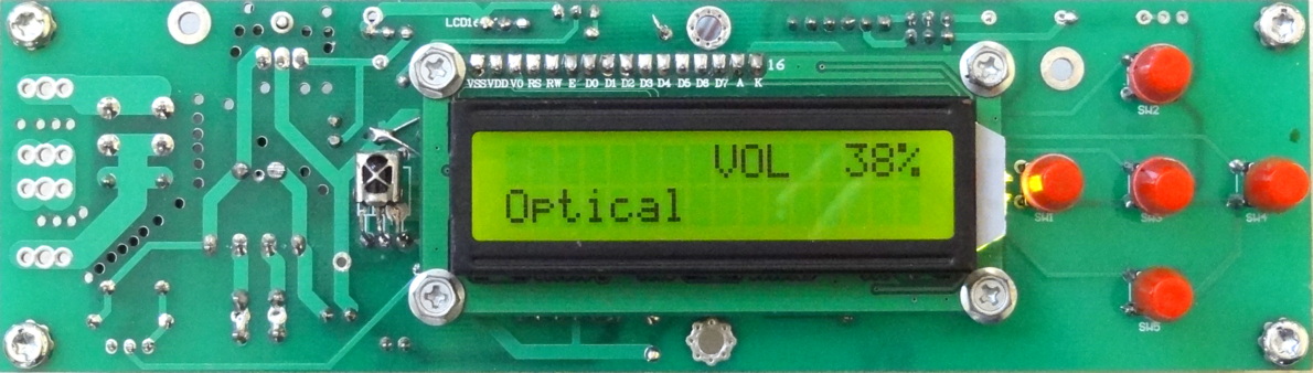
6. Cool LCD display of Input mode, temperatures of both channels and status with warning
7. LED display of faulty conditions with flashing speed
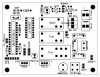
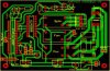
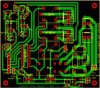
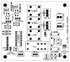
8. Main PCB + 5 key input PCB with component layout in expressPCB
The components used are:
1. 4 channel Input selector from theaudiocrafts - theaudiocrafts
2. Motorized Alps pot from the above dealer
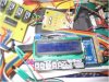
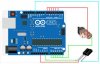
3. Arduino Mega with LCD display from Sainsmart
4. Input keys micro switches with cap from Mx
5. IR - TSOP 48386.
6. 12V DC Fan
7. Remotes as mentioned in my previous post
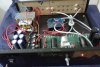
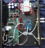
The photos I have shown are of the prototype and not the final product. The Arduino Mega with LCD display to be attached to the front panel with keyboard. The soft start module and input selector are to be attached to the back panel.
If any needs the .pcb files on expressPCB, I would be happy to email them.
I will be posting one more IR related project i.e. control of the entire Music system including Home theatre and LCD Projector , fan and light control with the same Remote so you can completely relax with a set of remotes, a mug of cold beer or whatever, a packet of snacks. And enjoy the music!

#include <IRremote.h>
#include <OneWire.h>
#include <DallasTemperature.h>
#include <LiquidCrystal.h>
LiquidCrystal lcd(8, 13, 9, 4, 5, 6, 7);

#define ONE_WIRE_BUS 50
OneWire oneWire(ONE_WIRE_BUS);
DallasTemperature sensors(&oneWire);
DeviceAddress L_temp = { 0x22, 0xFB, 0x10, 0x2C, 0x00, 0x00, 0x00, 0x01 };
DeviceAddress R_temp = { 0x22, 0x74, 0x19, 0x2C, 0x00, 0x00, 0x00, 0x3C };

// Arduino Mega pins 21,23,25 motor up; 27,29,31 motor down
// Arduino Mega pins 36 to LED; pin 49 to IR sensor; +5v and GND pins to sensor and GND pin to LED

int RECV_PIN = 49;
long oldValue; // This value will save the last meaningful remote input and reuse it in the case of a repeat
int volDelay = 175; //this value can be changed to move volume for longer increments

const int CD_BUTTON = 37;
const int TUNER_BUTTON = 39;
const int TV_BUTTON = 41;
const int MP_BUTTON = 43;


const int CD_RLY = 38;
const int TUNER_RLY = 40;
const int TV_RLY = 42;
const int MP_RLY = 44;


const int SPK_IN_L = 22;
const int SPK_IN_R = 24;
const int PWR_BUTTON = 34;
const int LED = 36;

const int SPK_RLY_L = 26;
const int SPK_RLY_R = 28;
const int FAN_RLY = 30;
const int PWR_RLY = 32;

const int SUBPH_BUTTON = 46;
const int SUBPH_RLY = 48;

int tempC = 0;
int LTemp = 0;
int RTemp = 0;

int SPK_R_VAL = 0;
int SPK_L_VAL = 0;
int CD_VAL = 0;
int CD_OLDVAL = 0;
int CD_STATE = 0;

int TUNER_VAL = 0;
int TUNER_OLDVAL = 0;
int TUNER_STATE = 0;

int TV_VAL = 0;
int TV_OLDVAL = 0;
int TV_STATE = 0;

int MP_VAL = 0;
int MP_OLDVAL = 0;
int MP_STATE = 0;

int PWR_VAL = 0;
int PWR_OLDVAL = 0;
int PWR_STATE = 0;

int SUBPH_VAL = 0;
int SUBPH_OLDVAL = 0;
int SUBPH_STATE = 0;

IRrecv irrecv(RECV_PIN);
decode_results results;

void setup(void) {
lcd.clear();
lcd.begin(16,2);
lcd.setCursor(0,1);
lcd.print("Spkr:OFF");
lcd.setCursor(9,1);
lcd.print("Pwr:OFF");
sensors.begin(); // starts temp sensors
Serial.begin(9600); // starts serial port
irrecv.enableIRIn(); // Start the IR receiver
pinMode(21,OUTPUT);
pinMode(23,OUTPUT); //setting power to motor pins for 5v output
pinMode(25,OUTPUT);

pinMode(27,OUTPUT);
pinMode(29,OUTPUT); //setting power to motor pins for 5v output
pinMode(31,OUTPUT);

MotorOff();

pinMode(CD_RLY, OUTPUT);
pinMode(TUNER_RLY, OUTPUT);
pinMode(TV_RLY, OUTPUT);
pinMode(MP_RLY, OUTPUT);
pinMode(PWR_RLY, OUTPUT);
pinMode(SPK_RLY_L, OUTPUT);
pinMode(SPK_RLY_R, OUTPUT);
pinMode(SUBPH_RLY, OUTPUT);

pinMode(CD_BUTTON, INPUT);
pinMode(TUNER_BUTTON, INPUT);
pinMode(TV_BUTTON, INPUT);
pinMode(MP_BUTTON, INPUT);
pinMode(PWR_BUTTON, INPUT);
pinMode(SPK_IN_R, INPUT);
pinMode(SPK_IN_L, INPUT);
pinMode(SUBPH_BUTTON, INPUT);
//pinMode(AC_IN, INPUT);

digitalWrite(CD_RLY, LOW);
digitalWrite(TUNER_RLY, LOW);
digitalWrite(TV_RLY, LOW);
digitalWrite(MP_RLY, LOW);
digitalWrite(PWR_RLY, LOW);
digitalWrite(SPK_RLY_L, LOW);
digitalWrite(SPK_RLY_R, LOW);
digitalWrite(SUBPH_RLY, LOW);
}

void loop(void) {
// check for IR power ON
if (irrecv.decode(&results)) {
if (results.value == 4105841032) {
lcd.setCursor(13, 1);
lcd.print(" ");
PWR_STATE = 1- PWR_STATE; delay(100);
PWR_OLDVAL = PWR_STATE;
if (PWR_STATE == 1) {
PWR_Press();
} else {
PWR_OFF();
}
irrecv.resume(); // Receive the next value
}

} else {
// check for PWR press
PWR_VAL = digitalRead(PWR_BUTTON);
if (PWR_VAL == HIGH) {
lcd.setCursor(13, 1);
lcd.print(" ");
PWR_STATE = 1- PWR_STATE; delay(100);
PWR_OLDVAL = PWR_STATE;
if (PWR_STATE == 1) {
PWR_Press();
} else {
PWR_OFF();
}
}
}
//check spkr volt
SPK_R_VAL = digitalRead(SPK_IN_R);
if (SPK_R_VAL == LOW) {
digitalWrite(SPK_RLY_R, LOW);
lcd.setCursor(0, 1);
lcd.print("SpkR:OFF");
LED_FLASH_500();
} else {
digitalWrite(SPK_RLY_R, HIGH);
lcd.setCursor(0, 1);
lcd.print("SpkR:ON ");
LED_ON();
}

SPK_L_VAL = digitalRead(SPK_IN_L);
if (SPK_L_VAL == LOW) {
digitalWrite(SPK_RLY_L, LOW);
lcd.setCursor(0, 1);
lcd.print("SpkL:OFF");
LED_FLASH_500();
} else {
digitalWrite(SPK_RLY_L, HIGH);
lcd.setCursor(0, 1);
lcd.print("SpkL:ON ");
LED_ON();
}

if (PWR_STATE == HIGH) {
if (irrecv.decode(&results)) {
Serial.println(results.value, DEC);
/////////////////////
if (results.value==1752382022) //if up button pushed move motor forward with a 250ms shot of 5V
{
oldValue=results.value; //setting the placeholders value
MotorUp();
delay(volDelay); //this value can be changed to move volume in bigger increments
MotorOff();
}

else if (results.value==2209452902) // down button pushed
{
oldValue =results.value;
MotorDown();
delay(volDelay);
MotorOff();
}
else if (results.value==0xFFFFFFFF) // button is held down, do the last thing done, again
{
if (oldValue==1752382022)
{
MotorUp();
delay(volDelay);
MotorOff();
}

else if (oldValue==2209452902)
{
MotorDown();
delay(volDelay);
MotorOff();
}
//}
///////////////////////////////////

switch (results.value) {
case 3778927144:
//Serial.println("CD");
CD_Press(); // selects CD
break;
case 2908251746:
//Serial.println("TUNER");
TUNER_Press(); // selects TUNER
break;
case 657459652:
//Serial.println("TV");
TV_Press(); // selects TV
break;
case 4120482440:
//Serial.println("MP");
MP_Press(); // selects MP
break;
case :
SUBPH_Press();
break;

//case 4105841032: // -1734753073:
//Serial.println("ON/OFF");
//PWR_Press(); // sets the PWR on
break;
default:
delay(100);
//Serial.println("Waiting ...");
}
irrecv.resume(); // Receive the next value
} else {

////////////////////////////

// check for MP button press
MP_VAL = digitalRead(MP_BUTTON);
if (MP_VAL == HIGH) {
MP_Press();
}
// check for TUNER button press
TUNER_VAL = digitalRead(TUNER_BUTTON);
if (TUNER_VAL == HIGH) {
TUNER_Press();
}
// check for TV button press
TV_VAL = digitalRead(TV_BUTTON);
if (TV_VAL == HIGH) {
TV_Press();
}
// check for CD button press
CD_VAL = digitalRead(CD_BUTTON);
if (CD_VAL == HIGH) {
CD_Press();
}
// check for Sub Ph button press
SUBPH_VAL = digitalRead(SUBPH_BUTTON);
if (SUBPH_VAL == HIGH) {
SUBPH_Press();
}
}
}
sensors.requestTemperatures();
printTemperature(L_temp);
printTemperature(R_temp);
}

void MotorOff() {
digitalWrite(21,LOW); // The core code for motor control came from http://www.hifivision.com/diy/44275-...g-arduino.html
digitalWrite(23,LOW); // this sets the functions for each mode of motor movement
digitalWrite(25,LOW);
digitalWrite(27,LOW);
digitalWrite(29,LOW);
digitalWrite(31,LOW);
}

void MotorUp(){
digitalWrite(21,HIGH); // The core code for motor control came from http://www.hifivision.com/diy/44275-...g-arduino.html
digitalWrite(23,HIGH); // this sets the functions for each mode of motor movement
digitalWrite(25,HIGH);
digitalWrite(27,LOW);
digitalWrite(29,LOW);
digitalWrite(31,LOW);
}

void MotorDown()
{
digitalWrite(21,LOW); // The core code for motor control came from http://www.hifivision.com/diy/44275-...g-arduino.html
digitalWrite(23,LOW); // this sets the functions for each mode of motor movement
digitalWrite(25,LOW);
digitalWrite(27,HIGH);
digitalWrite(29,HIGH);
digitalWrite(31,HIGH);
}

void printTemperature(DeviceAddress deviceAddress)
{
int tempL = sensors.getTempC(L_temp);
int tempR = sensors.getTempC(R_temp);
if (tempC == -127.00) {
lcd.setCursor(10,0);
lcd.print(" Err");
} else {
lcd.setCursor(10,0);
lcd.print(tempL);
lcd.setCursor(13,0);
lcd.print(tempR);
lcd.print("C");

if (tempL > 50 | tempR > 50) {
digitalWrite(FAN_RLY, HIGH);
LED_FLASH_1000();
lcd.setCursor(6,0);
lcd.print("FAN");
} else {
lcd.setCursor(6,0);
lcd.print(" ");
digitalWrite(FAN_RLY, LOW);
LED_ON();
}
if (tempL > 60 | tempR > 60) {
digitalWrite(SPK_RLY, LOW);
lcd.setCursor(6,0);
lcd.print("HOT");
lcd.setCursor(0,1);
lcd.print("Spkr:OFF");
}
}
}

void SUBPH_Press() {
SUBPH_STATE = 1 - SUBPH_STATE; delay(150);
SUBPH_OLDVAL = SUBPH_VAL;
if (SUBPH_STATE == 1) {
digitalWrite(SUBPH_RLY, HIGH);
} else {
digitalWrite(SUBPH_RLY, LOW);
}
}

void CD_Press() {
CD_STATE = 1- CD_STATE; delay(500);
CD_OLDVAL = CD_VAL;
if (CD_STATE == 1) {
TUNER_VAL = 0; TUNER_OLDVAL = 0; TUNER_STATE = 0; digitalWrite(TUNER_RLY,LOW);
TV_VAL = 0; TV_OLDVAL = 0; TV_STATE = 0; digitalWrite(TV_RLY,LOW);
MP_VAL = 0; MP_OLDVAL = 0; MP_STATE = 0; digitalWrite(MP_RLY,LOW);
delay(500);
digitalWrite(CD_RLY, HIGH);
lcd.setCursor(0, 0);
lcd.print("DVD ");
} else {
lcd.setCursor(0, 0);
lcd.print(" ");
digitalWrite(CD_RLY, LOW);
}
}

void MP_Press() {
lcd.setCursor(0, 0);
lcd.print(" ");
MP_STATE = 1- MP_STATE; delay(10);
MP_OLDVAL = MP_VAL;
if (MP_STATE == 1) {
CD_VAL = 0; CD_OLDVAL = 0; CD_STATE = 0; digitalWrite(CD_RLY,LOW);
TV_VAL = 0; TV_OLDVAL = 0; TV_STATE = 0; digitalWrite(TV_RLY,LOW);
TUNER_VAL = 0; TUNER_OLDVAL = 0; TUNER_STATE = 0; digitalWrite(TUNER_RLY,LOW);
delay(500);
lcd.setCursor(0, 0);
lcd.print("MP ");
digitalWrite(MP_RLY, HIGH);
} else {
lcd.setCursor(0, 0);
lcd.print(" ");
digitalWrite(MP_RLY, LOW);
}
}

void TUNER_Press() {
TUNER_STATE = 1- TUNER_STATE; delay(100);
TUNER_OLDVAL = TUNER_VAL;
if (TUNER_STATE == 1) {
CD_VAL = 0; CD_OLDVAL = 0; CD_STATE = 0; digitalWrite(CD_RLY,LOW);
TV_VAL = 0; TV_OLDVAL = 0; TV_STATE = 0; digitalWrite(TV_RLY,LOW);
MP_VAL = 0; MP_OLDVAL = 0; MP_STATE = 0; digitalWrite(MP_RLY,LOW);
delay(500);
digitalWrite(TUNER_RLY, HIGH);
lcd.setCursor(0, 0);
lcd.print("TUNER");
} else {
lcd.setCursor(0, 0);
lcd.print(" ");
digitalWrite(TUNER_RLY, LOW);
}
}

void TV_Press() {
TV_STATE = 1- TV_STATE; delay(100);
TV_OLDVAL = TV_VAL;
if (TV_STATE == 1) {
CD_VAL = 0; CD_OLDVAL = 0; CD_STATE = 0; digitalWrite(CD_RLY,LOW);
TUNER_VAL = 0; TUNER_OLDVAL = 0; TUNER_STATE = 0; digitalWrite(TUNER_RLY,LOW);
MP_VAL = 0; MP_OLDVAL = 0; MP_STATE = 0; digitalWrite(MP_RLY,LOW);
delay(500);
lcd.setCursor(0, 0);
lcd.print("TV ");
digitalWrite(TV_RLY, HIGH);
} else {
lcd.setCursor(0, 0);
lcd.print(" ");
digitalWrite(TV_RLY, LOW);
}
}

void PWR_Press() {
digitalWrite(PWR_RLY, HIGH);
lcd.setCursor(13, 1);
lcd.print(" ON");
SPK_VAL == digitalRead(SPK_IN);
if (SPK_VAL == HIGH) {
lcd.setCursor(0, 0);
lcd.print("Wait..");
delay(5000);
digitalWrite(SPK_RLY, HIGH);
lcd.setCursor(0, 1);
lcd.print("Spkr: ON");
lcd.setCursor(0, 0);
lcd.print(" ");
} else {
digitalWrite(SPK_RLY, LOW);
lcd.setCursor(0, 1);
lcd.print("Spkr:OFF");
}
}

void PWR_OFF() {
CD_VAL = 0; CD_OLDVAL = 0; CD_STATE = 0; digitalWrite(CD_RLY,LOW);
TV_VAL = 0; TV_OLDVAL = 0; TV_STATE = 0; digitalWrite(TV_RLY,LOW);
TUNER_VAL = 0; TUNER_OLDVAL = 0; TUNER_STATE = 0; digitalWrite(TUNER_RLY,LOW);
MP_VAL = 0; MP_OLDVAL = 0; MP_STATE = 0; digitalWrite(MP_RLY,LOW);
digitalWrite(PWR_RLY, LOW);
lcd.clear();
lcd.setCursor(9, 1); lcd.print("Pwr:OFF");
lcd.setCursor(0, 1); lcd.print("Spkr:OFF");
}

void LED_FLASH_1000(){
digitalWrite(LED,HIGH);
delay(1000);
digitalWrite(LED,LOW);
delay(1000);
}

void LED_FLASH_500(){
digitalWrite(LED,HIGH);
delay(500);
digitalWrite(LED,LOW);
delay(500);
}

void LED_ON(){
digitalWrite(LED,HIGH);
}
 

Attachments

  • Complete_Stereo_Control.jpg
    Complete_Stereo_Control.jpg
    21.2 KB · Views: 183
  • Complete_Stereo_Control_Comp.jpg
    Complete_Stereo_Control_Comp.jpg
    19.6 KB · Views: 177
  • 5KeyBoard.jpg
    5KeyBoard.jpg
    21.5 KB · Views: 172
  • 5KeyBoardComp.jpg
    5KeyBoardComp.jpg
    17.3 KB · Views: 175
  • CompleteStreoControlPrototype.jpg
    CompleteStreoControlPrototype.jpg
    21.5 KB · Views: 183
Thanks for your suggestion. But getting a five in row keypad would be difficult or you would have to have non-used keys or find some function for them. It would be not too difficult to incorporate this touch switch. It would look sleek anyways.
 
MPR121QR2 chip in the module has 12 INPUTS! all need not to be used

to avoid clutter .. all you need is a pcb
KITMPR121EVM.jpg

here we can have a felxiplastic sticker to make it beautiful.. 3 of my UNO clones awaiting for some new builds

need to match freetime+freemind for that!
 
I have used TSOP4838 for the IR sensor and a Samsung TV remote. DS1882 x 2 for sensing temperature in both heatsinks. courtesy arduino.cc

Is DS1882 a temperature sensor or digital potentiometer? when searching info for DS1882 it shows as a digital potentiometer (digital control analog pot)


you can do away with 100rs bare bones ARduino :) I will post later how to .
DAC voltage to the lightspeed photo attenuator is another way to achive quality
volume on remote .

A nice looking LCD will be cool
dsc03359.jpg

Hi kaushik,

Could you please give more info on arduino controlled light speed photo attenuator?

thanks and regards
S Sarath
 
When I wanted to control the Motorized ALPS pot for my PASS B1, I started
doing research and found that most MCUs used a H-Bridge using PNP+NPN transistors or HBridge ICs to drive the motor bidirectionally.

Then by chance I came across this article in elektor.
http://dr-shost.com/files/article.pdf

Here elektor guys have used a MCU IO Pins to drive the motor directly. Their calculation is that One ATMega IO Pin is capable of sourcing or sinking 20ma so you can connect 6 IO pins in parallel to source or sink 120ma. Since the ALPS motor requires only 100 ma for movement this should be more than sufficient. We also don't run the motor continuously, we run it only in 50ms steps.

I followed this idea and was able to drive my ALPS pot without any external components.
I have used A0-A5 ports of the arduino for one terminal of the motor and Pins 2-7 for the
other, now from the program its just a matter of setting one set of Pins to High and other
to Low to move the motor either-way. I have not included any end detection circuits /code since this pot has a slip clutch which does not damage the motor when it reaches either end.

For IR Remote I have used the library from

https://github.com/shirriff/Arduino-IRremote

I have attached the sketch.

The Sketch also prints the type of the remote and the keycode received.
For customizing to your remote, press the keys and notedown the keycode printed in the Arduino IDE serial console. Next you can just change the values in the if command in the loop() function to match the keys noted.

There are extra 4 IOs left (8,9,10,11) These can be used to switch the input
on the input selector board.

Sketch : http://g-box.in//Downloads/Private/gArduinoRemote.zip
Hi KiranPS,
I'm interested in your sketch of this project, but it seems that it isn't available anymore. I don't have many experience with coding and i'd like to use your sketch as an example. Would you re-upload the files? :) thanks!
 
Hi KiranPS,
I'm interested in your sketch of this project, but it seems that it isn't available anymore. I don't have many experience with coding and i'd like to use your sketch as an example. Would you re-upload the files? :) thanks!
Hi Tahner,

I have re uploaded to github.


Warm Regds,
Ravi Kiran.
 
Follow HiFiMART on Instagram for offers, deals and FREE giveaways!
Back
Top