@tcpip, sublime finish! Was the bevelling made for aesthetics alone or does that influence the SQ?
You are using an out of date browser. It may not display this or other websites correctly.
You should upgrade or use an alternative browser.
You should upgrade or use an alternative browser.
The Darbari: new speaker project
- Thread starter tcpip
- Start date
It may have some acoustic benefits for the tweeter, to reduce edge reflections. Even this bit is not an universally accepted theory I am told. But other than that, I chose to use it for aesthetics. With boxes this big, the bevelling, and the tapering of the bevel top and bottom, reduces the boxiness of the appearance. I have tried to enhance the effectiveness of this tapered bevelling trick by using a darker veneer for the front surface and lighter ones for the rest, to accentuate the bottle-like shapes. Don't know whether some other approach would have yielded better results, but I am happy that the boxes look less boxy than plain rectangular prisms would have.@tcpip, sublime finish! Was the bevelling made for aesthetics alone or does that influence the SQ?
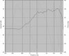
Now that the enclosures are done, the second Hard Part (TM) starts. The SPL measurements are done, the crossovers need to be designed.
This is the tweeter SPL:

And this is the midrange SPL:

All taken at one meter distance using my usual measurement setup, pointing the mic at a point between the tweeter and the midrange.
Any of you who want to have a go at designing and modelling crossovers, just ask, and I'll upload the FRD files. ZMA files will not be needed, because I am doing an active line-level xo. I may still take impedance measurements, just out of curiosity and to see what resonances and ringing I can see (as unevennesses in the impedance curves).
I can see that lots of notch filters will now be deployed on the midrange.
This is the tweeter SPL:
And this is the midrange SPL:
All taken at one meter distance using my usual measurement setup, pointing the mic at a point between the tweeter and the midrange.
Any of you who want to have a go at designing and modelling crossovers, just ask, and I'll upload the FRD files. ZMA files will not be needed, because I am doing an active line-level xo. I may still take impedance measurements, just out of curiosity and to see what resonances and ringing I can see (as unevennesses in the impedance curves).
I can see that lots of notch filters will now be deployed on the midrange.
Last edited:
kapvin
Well-Known Member
Now that the enclosures are done, the second Hard Part (TM) starts. The SPL measurements are done, the crossovers need to be designed.
This is the tweeter SPL:
And this is the midrange SPL:
All taken at one meter distance using my usual measurement setup, pointing the mic at a point between the tweeter and the midrange.
Any of you who want to have a go at designing and modelling crossovers, just ask, and I'll upload the FRD files. ZMA files will not be needed, because I am doing an active line-level xo. I may still take impedance measurements, just out of curiosity and to see what resonances and ringing I can see (as unevennesses in the impedance curves).
I can see that lots of notch filters will now be deployed on the midrange.
while I am not able to post often, I just have a quick comment based on the graphs you posted.
Of course, I could be totally wrong, but based on the roll off below 1 khz (and the spiky response for both FR and phase) for your mid, i'd say you used a very narrow gate. and you are losing resolution in your measurement. you will probably need to use a larger measuring gate. if there is something I've missed or misread, please do let me know.
Also, given the distance between the drivers you'd need to decide on where you want the response to sum and then measure from there to get driver Z offset. (if only to get the Z offset). it might vary more than what you want from what you measure at 1 m.
this is actually the most fun and most painful part of the build, all at once.. hope you have only fun..
BTW, really nice work on the cabinets. would have loved to listen.
These days, I never measure SPL directly -- I measure impulse and then convert from impulse to SPL. This lets me take one measurement and play at leisure with various gating positions. These gatings were arrived at by experiment, and these are about as smooth as I can get the SPL curve to be.Of course, I could be totally wrong, but based on the roll off below 1 khz (and the spiky response for both FR and phase) for your mid, i'd say you used a very narrow gate. and you are losing resolution in your measurement. you will probably need to use a larger measuring gate. if there is something I've missed or misread, please do let me know.
The phase response spikiness is not an indicator of a measurement problem -- the spikiness will go away if I just add a delay offset in Speaker Workshop to arrive at minimum phase. I used to add that delay before reporting the graphs, but I later realised that the cleaning up of the phase graph is just an aesthetic thing -- it doesn't affect anything else, so I let it remain these days.
The gate I am using is limited by the distance from the speaker to the mic anyway -- I need to gate out the first reflection (which in my case is from the floor). I can't, say, double the gate duration, due to physical constraints.
Squiggles in the SPL curve usually indicate early reflections from somewhere or other. These could be imperfections in the driver mounting -- e.g. the recess having a half-mm or 1-mm unevenness in the front baffle, thus reflecting tweeter output from the edge between the tweeter's front plate and the baffle recess edge. A "perfectly recessed" baffle and a "perfectly mounted" tweeter would eliminate these squiggles. Again, I've learned to ignore these because they don't have a material effect on the crossover design, once the enclosures are made and you know you have to live with the tiny imperfections in the recessing.
FWIW, all my earlier measurements were with the Asawari series of speakers, and they were all MTM designs. There, the two midbass units would reflect the tweeter sound waves, resulting in more squiggles. These tweeter readings for the Darbari are cleaner.
")
Frankly, I don't think this thing matters. The point where I put my mic should ideally be at the listening position. That would be more than two metres away, given my living room. I cannot afford to put the mic there due to room reflections. Therefore, the 1 metre distance is a good compromise. After all, any mic position is a compromise once you realise that the listener's head will never be exactly at the mic position in real life. Once this is understood, all that we are doing is making sure that the tweeter and midrange are summing in phase correctly, with matching SPL, at some reasonable position, any position (within limits).Also, given the distance between the drivers you'd need to decide on where you want the response to sum and then measure from there to get driver Z offset. (if only to get the Z offset). it might vary more than what you want from what you measure at 1 m.
Driver Z offset is the difference (loosely speaking) between the distances of the two drivers' acoustic centres from the mic. That difference remains the same whether you measure at 1 metre or 2 metres. If you measure at 30 cm, then you are measuring sharply off-axis for one or both drivers, and that would have been a problem. But you are barely a few degrees off-axis when you measure at 1 metre, and you will be 1-2 degrees closer to on-axis when you measure at 2 metres. This small a difference won't make a material difference to the crossover design. Remember, in a Real Life (TM) scenario, people will listen to the speakers standing up, sitting down, sitting on the couch to one side, etc. How will you cater to their perceptions?
Therefore, IMHO, the only things to take care of are:
- the mic must be in exactly the same position for the two driver measurements
- the signal level fed to the two drivers must be exactly the same -- don't touch the gain controls between measurements
- the delay or latency of your sound card and mic preamp, etc, must be exactly the same for both measurements, or else your SPL curves will be individually correct, but their relative phase relationship will be wrong.
- try to be pretty much on-axis for both drivers, therefore a minimum distance of about a metre is needed
Hah! Famous last words! :sad:this is actually the most fun and most painful part of the build, all at once.. hope you have only fun..
In any case, I will do a second round of measurements at two metres, and will do near-field measurements of the midrange and woofer. "Kahaani abhi bhi baaki hai."
When are you dropping by?BTW, really nice work on the cabinets. would have loved to listen.
There may even be some Amarula left when you come. BTW, I never try to get the driver Z offset. It is not necessary.Also, given the distance between the drivers you'd need to decide on where you want the response to sum and then measure from there to get driver Z offset. (if only to get the Z offset). it might vary more than what you want from what you measure at 1 m.
If I take measurements the way I have described above, then the driver Z offset is effectively zero for my purposes, because the two signals I am measuring are "in sync", phase-wise. In other words, I don't care whether there is a physical offset in the acoustic centres of a few inches -- I am already getting the effect of that offset in the relative phases of the two signals at the mic position. Therefore, no separate delay needs to be added to the digital crossover (or any other correction in an analog crossover) to correct for Z offset. It's already being accounted for when I ensure that the drivers are in phase, by reversing one of them and ensuring that I am getting a deep notch at crossover point.
kapvin
Well-Known Member
These days, I never measure SPL directly -- I measure impulse and then convert from impulse to SPL. This lets me take one measurement and play at leisure with various gating positions. These gatings were arrived at by experiment, and these are about as smooth as I can get the SPL curve to be.
The phase response spikiness is not an indicator of a measurement problem -- the spikiness will go away if I just add a delay offset in Speaker Workshop to arrive at minimum phase. I used to add that delay before reporting the graphs, but I later realised that the cleaning up of the phase graph is just an aesthetic thing -- it doesn't affect anything else, so I let it remain these days.
The gate I am using is limited by the distance from the speaker to the mic anyway -- I need to gate out the first reflection (which in my case is from the floor). I can't, say, double the gate duration, due to physical constraints.
Squiggles in the SPL curve usually indicate early reflections from somewhere or other. These could be imperfections in the driver mounting -- e.g. the recess having a half-mm or 1-mm unevenness in the front baffle, thus reflecting tweeter output from the edge between the tweeter's front plate and the baffle recess edge. A "perfectly recessed" baffle and a "perfectly mounted" tweeter would eliminate these squiggles. Again, I've learned to ignore these because they don't have a material effect on the crossover design, once the enclosures are made and you know you have to live with the tiny imperfections in the recessing.
FWIW, all my earlier measurements were with the Asawari series of speakers, and they were all MTM designs. There, the two midbass units would reflect the tweeter sound waves, resulting in more squiggles. These tweeter readings for the Darbari are cleaner.
Frankly, I don't think this thing matters. The point where I put my mic should ideally be at the listening position. That would be more than two metres away, given my living room. I cannot afford to put the mic there due to room reflections. Therefore, the 1 metre distance is a good compromise. After all, any mic position is a compromise once you realise that the listener's head will never be exactly at the mic position in real life. Once this is understood, all that we are doing is making sure that the tweeter and midrange are summing in phase correctly, with matching SPL, at some reasonable position, any position (within limits).
Driver Z offset is the difference (loosely speaking) between the distances of the two drivers' acoustic centres from the mic. That difference remains the same whether you measure at 1 metre or 2 metres. If you measure at 30 cm, then you are measuring sharply off-axis for one or both drivers, and that would have been a problem. But you are barely a few degrees off-axis when you measure at 1 metre, and you will be 1-2 degrees closer to on-axis when you measure at 2 metres. This small a difference won't make a material difference to the crossover design. Remember, in a Real Life (TM) scenario, people will listen to the speakers standing up, sitting down, sitting on the couch to one side, etc. How will you cater to their perceptions?
Therefore, IMHO, the only things to take care of are:
That's about it, I feel.
- the mic must be in exactly the same position for the two driver measurements
- the signal level fed to the two drivers must be exactly the same -- don't touch the gain controls between measurements
- the delay or latency of your sound card and mic preamp, etc, must be exactly the same for both measurements, or else your SPL curves will be individually correct, but their relative phase relationship will be wrong.
- try to be pretty much on-axis for both drivers, therefore a minimum distance of about a metre is needed
Hah! Famous last words! :sad:
In any case, I will do a second round of measurements at two metres, and will do near-field measurements of the midrange and woofer. "Kahaani abhi bhi baaki hai."
When are you dropping by?
I never ever used speaker workshop so I cannot comment on the features / limitations. I do get smoother curves with all the other measurement software. you will be suprised at the amount of squiggles a 0.5mm difference between the speaker frame and the baffle can cause. and it is realworld. equally, you baffle will cause squiggles in your response based on baffle width and rounder over used. Again, real world. Finally, all responses we see on speaker spec sheets are smoothed.. realworld has squiggles.. many squiggles are minor and can be ignored, but sometimes there is a deeper dip / spike that needs to be corrected.
re: measurement .. I think I could not get my point across, when you gate, you lose resolution. try close mic-ing with a larger gate and you'll understand what i mean. (this is especially true for diffraction artifacts)
I understand your point about real world stereo, but eventually, every speaker has a design axis, (you should measure on axis, but optimise response for off axis)
I do derive distances from my listening position. digital crossovers allow for perfect time coherence, easy to achieve, so why miss that point?
I did not understand your point about delay / latency. Of course your measurement position must be constant as must be the electronic chain. therefore you must have your minidsp inline (but set to flat, no processing or crossover or delay)
ACD ( I assume that is what you are using) requires Z- offset for accurate modelling. you will also have the agony of running full range signals unfiltered through your tweeters.
finally, ACD will require you to have a minphase file.
when I come to India next, I will try to drop in. I now live in the land of Amarula, so maybe I'll bring in a bottle
I do not want to hijack your thread so if you are interested, over mail we can exchange .frds and ACD files, you'll see what measurements i got (Same family but different models) and the final filter solutions that I came up with.
Last edited:
Yes, I know these squiggles are real-world, but I meant that they can be ignored -- they don't need to be fussed over while designing the crossover. If I was building a laboratory transducer instead of a speaker for home music listening, I'd go that extra mile for perfect alignment of the recesses and edges.I never ever used speaker workshop so I cannot comment on the features / limitations. I do get smoother curves with all the other measurement software. you will be suprised at the amount of squiggles a 0.5mm difference between the speaker frame and the baffle can cause. and it is realworld. equally, you baffle will cause squiggles in your response based on baffle width and rounder over used. Again, real world. Finally, all responses we see on speaker spec sheets are smoothed.. realworld has squiggles.. many squiggles are minor and can be ignored, but sometimes there is a deeper dip / spike that needs to be corrected.
Talking about smoothed SPL curves, I've attached one here -- the same tweeter response, smoothed at 1/10 octave and with the phase data "cleaned up" by removing excess delay (one click of a button on Speaker Workshop). The smoothed curve looks prettier, but either one, smoothed or raw, may be used for crossover design with almost the same results, once you know not to over-correct for the squiggles.
Yes, you're absolutely right. Except that when you close-mic, you don't get the relative phase between the drivers, therefore you need to take an additional reading gated, from far away (like a metre or two), to get the relative phases of the drivers. That's the part needed to get relative driver offset.re: measurement .. I think I could not get my point across, when you gate, you lose resolution. try close mic-ing with a larger gate and you'll understand what i mean. (this is especially true for diffraction artifacts)
There's a second reason not to use nearfield measurements for crossover design. Nearfield readings may not (will not?) show baffle effects. Therefore, nearfield readings will only show the raw output of the driver, not what's happening to that output due to baffle edges and other stuff a few inches away from the mic. This is a potentially serious omission for tweeters, because you must always design your crossover to take into account driver+baffle combo. It's totally a non-issue for woofers.
True. Whatever position you use for your gated farfield measurements is your design axis. My reason for my comments in my previous post is that choice of design axis is not very critical. Some people make a religion out of being on-axis on the tweeter, some say you must be on-axis on the midrange in a 3-way, etc, etc. I am not too fussy about that -- maybe I am a less precise designer.I understand your point about real world stereo, but eventually, every speaker has a design axis, (you should measure on axis, but optimise response for off axis)
However, I agree that being on-axis on the tweeter is a much more important thing for MTM designs than for Darbari-type things.
True.I do derive distances from my listening position. digital crossovers allow for perfect time coherence, easy to achieve, so why miss that point?
Answer: laziness, and unfamiliarity with the MiniDSP toolchain, I guess.
No need to have the MiniDSP in the measurement-time signal path, if you assume that it will add exactly the same delay for all output paths. (And in fact, this assumption is very important, or else the entire point of phase-coherent crossover design falls apart.)I did not understand your point about delay / latency. Of course your measurement position must be constant as must be the electronic chain. therefore you must have your minidsp inline (but set to flat, no processing or crossover or delay)
My earlier point about not bothering about driver Z-offset is basically that you don't need to have any separate step to derive or measure driver Z-offset if you do your basic work with gated farfield measurements keeping the mic at a constant position for both drivers.
Let us keep aside digital active xo for a moment and go into the world of passive power-level xo (the traditional stuff). In that type of xo, you don't get a chance to feed in any delay into any digital control panel -- you need to design your xo to get the drivers to time-align at the Fc. How do you do that?
This is easily achieved if you (i) take measurements with a fixed mic for both drivers, and (ii) ensure that your signal chain latency is constant for both readings. If you ensure these two, then your woofer and tweeter data already is carrying their real relative phase. I don't know how to explain this any more. You you can just take these SPL curves into Speaker Workshop, SoundEasy, LspCAD, whatever, and add capacitors and inductors happily. The xo modelling software will constantly model the effect of the summed SPL taking the phase into account. Therefore, if you are getting a flat(-tish) SPL curve when summing in phase, and a deep notch when summing anti-phase, then you know that the outputs from the drivers will be in phase at the crossover point. No separate measurement or corrective action needed to actually get the Z-offset.
I wil take it one step further. If you just plug in a stock LR4 lowpass on one side and LR4 highpass on the other, and optimise the values to get the acoustic slopes to match your spec, then you will almost automatically get a phase-coherent crossover which will give a deep anti-phase null. I have seen friends design crossovers for simple two-way systems literally in ten minutes this way, bar the tweaking. No Z-offset knowledge needed.
That's all I was trying to say: you don't need to derive, measure, or calculate Z-offset of your drivers to design a phase-coherent crossover. The Z-offset is already "factored in" if you take both readings from a stationary mic.
No, ACD does not require Z-offset separately for accurate modelling. It requires that you either feed in FRD data which is phase-related, or that you figure out the Z-offset in a separate step if your FRD data happens to not be phase-related. If I use the gated measurements which I have taken, and use them for xo modelling in ACD, I don't need to do anything about Z-offset. If however, I use your method of doing ungated nearfield measurements separately for each driver, then my mic position will not be constant across driver measurements, and then I will definitely need to do an extra step to get the Z-offset correct.ACD ( I assume that is what you are using) requires Z- offset for accurate modelling.
How else do you measure tweeter SPL? I have always run full-range MLS pulses through each driver for all my measurements since the time I learned to measure SPL.you will also have the agony of running full range signals unfiltered through your tweeters.
Don't know what this means. ACD calculates phase data from the magnitude data using Hilbert-Bode transform, I thought? Does the phase information in the file really matter to ACD?finally, ACD will require you to have a minphase file.
Yes, I'd noticed. Why else do you think I'd offered you Amarula instead of some single-malt or Kahlua?I now live in the land of Amarula, so maybe I'll bring in a bottle

IMHO, your posts are the most on-topic I can hope to get. And thanks for taking the time.I do not want to hijack your thread so if you are interested, over mail we can exchange .frds and ACD files, you'll see what measurements i got (Same family but different models) and the final filter solutions that I came up with.
Attachments
Last edited:
I read up a little more about minimum phase and crossover design and Z-offset.
It seems that there's "measured phase" (of the kind I get when i measure with a mic) and "derived phase" (which is derived from the magnitude data using Hilbert Bode). The "measured phase" is valuable if you are designing a crossover, because the measured phase data of the two drivers will take their Z-offset into account exactly. Thus, your crossover modelling will know exactly how in-phase the summed SPL is and how deep the anti-phase notch is. In other words, you can safely build the crossover based on the modelled behaviour, then measure the final system with one driver anti-phase, and you will actually see the SPL notch, thereby indicating that your drivers are in phase at the crossover point.
However, some crossover design software allow you to upload FRD data and specify whether you want it to pick up just the magnitude data or also the phase data. If you omit the phase data from the FRD, then you are left with "derived phase", which will be of no use to correlate the phases (and impact of Z-offset) of two separate drivers.
In this context, the "minphase" requirement of a crossover modeling software is incidental -- you can have "measured phase" data which is not "min-phase" and that should be fine. Provided the latency/offset/delay of both drivers is the same.
Am reading this forum thread and finding it quite useful...
kapvin
Well-Known Member
I read up a little more about minimum phase and crossover design and Z-offset.
It seems that there's "measured phase" (of the kind I get when i measure with a mic) and "derived phase" (which is derived from the magnitude data using Hilbert Bode). The "measured phase" is valuable if you are designing a crossover, because the measured phase data of the two drivers will take their Z-offset into account exactly. Thus, your crossover modelling will know exactly how in-phase the summed SPL is and how deep the anti-phase notch is. In other words, you can safely build the crossover based on the modelled behaviour, then measure the final system with one driver anti-phase, and you will actually see the SPL notch, thereby indicating that your drivers are in phase at the crossover point.
However, some crossover design software allow you to upload FRD data and specify whether you want it to pick up just the magnitude data or also the phase data. If you omit the phase data from the FRD, then you are left with "derived phase", which will be of no use to correlate the phases (and impact of Z-offset) of two separate drivers.
In this context, the "minphase" requirement of a crossover modeling software is incidental -- you can have "measured phase" data which is not "min-phase" and that should be fine. Provided the latency/offset/delay of both drivers is the same.
Am reading this forum thread and finding it quite useful...
i was going to respond to your earlier post, but then I saw this one.
You will have to pardon me, i spend so much time typing in my real job, that I tend to get terse to the point of being cryptic in non work written communication.
I had assumed that you knew about minphase so left the sentence like that. You have to extract the minimum phase from your frd. into a new FRD and feed it into ACD. otherwise you will not get the output you want (see, I am still terse?).
As far as Z offset is concerned, if you have set up the acd sheets and linked them, just add a bit of delay to one or 2 drivers (z offset) and see how the summed response changes (which you will use to model anyway). I think you'll agree that the extra bit of precision will help you a lot. (Driverinfo tab - column G 5-12)
Again on my point on resolution, what is the FFT size you are using?
You will have to pardon me, i spend so much time typing in my real job, that I tend to get terse to the point of being cryptic in non work written communication.
I could be wrong, but I don't think this is necessary. Not in the approach I have described as my way of crossover modelling. However, if I was measuring my drivers using the nearfield measurement method, then I would need to do all this, because the relative phase information between the drivers would need to be "generated" (if I may use the term) by first cleaning out the phase data of each driver, then taking the in-parallel SPL measurement, and then playing with the delay of the individual drivers and matching their sum with the in-parallel measurement.I had assumed that you knew about minphase so left the sentence like that. You have to extract the minimum phase from your frd. into a new FRD and feed it into ACD. otherwise you will not get the output you want (see, I am still terse?).
And min-phase simply involves removing excess delay from the phase data, as far as I can see. Not a big deal, but omitting it does not change the final crossover model you arrive at.
The summed response will obviously change if you time shift one driver with respect to the other. No doubts at all. But where is the loss of precision in the approach I am taking? IMHO it is as precise as possible, given my measurement rig. In fact, the ACD approach of match-the-graph may be less precise -- you have to depend on eyeball comparison.As far as Z offset is concerned, if you have set up the acd sheets and linked them, just add a bit of delay to one or 2 drivers (z offset) and see how the summed response changes (which you will use to model anyway). I think you'll agree that the extra bit of precision will help you a lot. (Driverinfo tab - column G 5-12)
Don't remember now. Will start up Speaker Workshop next time and will definitely let you know.Again on my point on resolution, what is the FFT size you are using?
Last edited:
Sample rate: 48 Ksamples/secAgain on my point on resolution, what is the FFT size you are using?
Sample size: 32 Ksamples
Therefore, precision and accuracy: 1 Hz to 24000 Hz, +/- 1.46 Hz
I checked the three documents which come with ACD -- the tutorial, the setup instructions, and the technical manual. The mention of minimum-phase FRD data is found only in the technical manual. And there, it is mentioned as "preferably" (see "What measurements should be used in the ACD tools", page 26 of the technical manual). As I had suspected, ACD does not require you to have a minphase file. It's nice to have minimum phase, but not mandatory. What's mandatory (my extrapolation) is accurate phase-aligned data, i.e. accurate capture of the relative phase between the drivers. In the absence of such data, one can generate min-phase data from the magnitude data using Hilbert-Bode transforms and then use the summed-response eyeball-matching to get the time alignment separately.finally, ACD will require you to have a minphase file.
Last edited:
kapvin
Well-Known Member
Sample rate: 48 Ksamples/sec
Sample size: 32 Ksamples
Therefore, precision and accuracy: 1 Hz to 24000 Hz, +/- 1.46 Hz
your sample is more than good enough, it's then down to the window size..
.how many discrete measurement points do you have in your FRD?
From what I remember from the data in the ACD spreadsheets, I think I have 256 rows in the FRD file.how many discrete measurement points do you have in your FRD?
Crossover between midrange and tweeter, version 1
Tried my hand at Active Crossover Designer for the first time, with the FRD data of the midrange and tweeter. This is what I can arrive at. You have to ignore all data below 1 KHz -- this is far-field gated data.
This is the summing of the drivers, crossing over at 1.5 KHz. I have to reverse the polarity of one driver to get this summation in this design.

This is what happens when the drivers' outputs are cancelling each other at the crossover point.

More details on my web page, giving full details of the filter parameters.
Tried my hand at Active Crossover Designer for the first time, with the FRD data of the midrange and tweeter. This is what I can arrive at. You have to ignore all data below 1 KHz -- this is far-field gated data.
This is the summing of the drivers, crossing over at 1.5 KHz. I have to reverse the polarity of one driver to get this summation in this design.
This is what happens when the drivers' outputs are cancelling each other at the crossover point.
More details on my web page, giving full details of the filter parameters.
Wharfedale Linton Heritage Speakers in Walnut finish at a Special Offer Price. BUY now before the price increase.
Similar threads
- Replies
- 29
- Views
- 5K