Active Bi-amp PCB

aniruddha82

Member
Joined
Apr 25, 2012
Messages
99
Points
18
Location
Pune
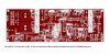
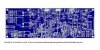
Just finished designing PCB for Active Bi-amp.
Features
1) LM3886 x 2 for Woofer (68W x 2)
2) LM1876 x 1 for Tweeter (20W x 2)
3) 2 x dual Regulated Power supply using LM338 and MUR860 ultra fast diodes to power 1 x LM1876 and 2 x LM3886
4) Speaker protection and delay using Relays
5) Preamp using NE5532
6) 2 way 24DB/octave LR active filter using NE5532
7) Provision for mounting stereo potentiometer for volume control on the board.
8) separate regulated power supply using LM7815 and LM7915 for active filter.
In process or ordering components for this, Will share component selection details later.
 

Attachments

  • biamp-top.jpg
    biamp-top.jpg
    20.9 KB · Views: 239
  • biamp-bot.jpg
    biamp-bot.jpg
    20.3 KB · Views: 238
Sorry for bad quality images, its due to size restriction by forum. Will upload hi-res images somewhere and will share link
 
Yes I believe that if housed in same cabinet and separated(the amp n crossover) it will yield less noise and if one or the other goes haywire then you can easily switch the out the pcbs accordingly instead desoldering and resoldering all of then again on a new board.

Also the crossover layout can follow esp's diagram layout of pcb which is actually better to acheive better sonics and less interference and avoid oscillation
 
Last edited by a moderator:
Also the crossover layout can follow esp's diagram layout of pcb which is actually better to acheive better sonics and less interference and avoid oscillation
Will take a look into it. Thanks.

Yes I believe that if housed in same cabinet and separated(the amp n crossover) it will yield less noise and if one or the other goes haywire then you can easily switch the out the pcbs accordingly instead desoldering and resoldering all of then again on a new board.
I never had problems with noise. It sounded amazing when there was no loose connections.
But I had loose connection problems many times after it was moved and shifted to other place. I understand if enclosure, markings and wires were connected in a neat manner I may not have faced problems, but it had became so complex that I have to open pcb design everytime I need to troubleshoot anything.
So I disassembled everything and redesigning now.
Thanks.
 
Last edited by a moderator:
Yes I believe that if housed in same cabinet and separated(the amp n crossover) it will yield less noise and if one or the other goes haywire then you can easily switch the out the pcbs accordingly instead desoldering and resoldering all of then again on a new board.
you are correct, i found few online resources describing cons of mixing signal and power ground. will research more but separating filter and amp PCBs looks like a good option now.
Thanks for your useful inputs.
 
No thanks needed. It helped you that is enough. Also if you make extra pcbs let me know I might need a few.
Yes sure, I will inform you and also post final PCB design before giving for manufacturing. I am redesigning with separate PCB for active filter and amplifiers and will make sure that high current in power ground does not come in the path of signal ground.
 
Nice!

I have few suggestions for this PCB.
  1. Make power supply traces little more wider. They around rectifiers and power capacitors.
  2. Separate ground plains for signal, power supply side. Top side ground plain is used least seems.
 
Nice!

I have few suggestions for this PCB.
  1. Make power supply traces little more wider. They around rectifiers and power capacitors.
  2. Separate ground plains for signal, power supply side. Top side ground plain is used least seems.
Many Thanks for your inputs, I am working on the same.

I am also planning few more changes on Power supply, Currently there are 2 separate dual power supply for both IC, Reason for this is both IC need different voltages.
I am thinking to remove bridge rectifier for LM1876 and get the power for lm1876 (which will be used by tweeter) from the first power supply and put a regulator again to lower the voltage. Drawback is pair of LM338 will share load for all amplifiers(2 x LM3886 + 1 x LM1876 + heat loss in LM317/337) But i think it should be sufficient as I am planning to use this for a low power bookshelf (M13KH + TL25SN).

Current Situation
Transformer - > Bridge Rectifier -> LM338 ->2 x LM3886
__________- > Bridge Rectifier -> LM338 ->1 x LM1876 (5A regulator is overkill for LM1876)

What is Planned
Transformer - > Bridge Rectifier -> LM338 ->2 x LM3886
___________________________________->LM317/337 ->1 x LM1876 (1.5A regulator is sufficient if used for tweeter)

Any thoughts and suggestions?

Thanks,
Anirudha
 
Last edited by a moderator:
I am also planning few more changes on Power supply, Currently there are 2 separate dual power supply for both IC, Reason for this is both IC need different voltages.
I am thinking to remove bridge rectifier for LM1876 and get the power for lm1876 (which will be used by tweeter) from the first power supply and put a regulator again to lower the voltage. Drawback is pair of LM338 will share load for all amplifiers(2 x LM3886 + 1 x LM1876 + heat loss in LM317/337) But i think it should be sufficient as I am planning to use this for a low power bookshelf (M13KH + TL25SN).

Current Situation
Transformer - > Bridge Rectifier -> LM338 ->2 x LM3886
__________- > Bridge Rectifier -> LM338 ->1 x LM1876 (5A regulator is overkill for LM1876)

What is Planned
Transformer - > Bridge Rectifier -> LM338 ->2 x LM3886
___________________________________->LM317/337 ->1 x LM1876 (1.5A regulator is sufficient if used for tweeter)

Any thoughts and suggestions?

Thanks,
Anirudha
Keep 5A regulators if it is used for power amplifier. They are required for peak loads.
LM337/317 are okay for small currents of pre, buffer or active crossover.
 
Keep 5A regulators if it is used for power amplifier. They are required for peak loads.
LM337/317 are okay for small currents of pre, buffer or active crossover.

You should be able to boost up the current output of the regulated Power supply by providing a power transistor in common collector configuration (say 2N3055). Connect the base to o/p of regulator IC and collector to the output of bridge + caps, the output would be from the emitter and would be about .6V less that the regulator o/p. You might already be knowing this but just an FYI.

Thanks,
Venki
 
Follow HiFiMART on Instagram for offers, deals and FREE giveaways!
Back
Top