Subbu68
Well-Known Member
Those who are tired of only hiss from their radios / tuners ( if you listen to) may try out this.
Rediscovered radio listening a few weeks back thanks to @santaji for his thread on Jetking Radio kits. Added a few more radios to my collection too.
Had been wanting to make a AM tuned loop to receive otherwise hard to get stations in apartments.
Finally managed to rig up one.
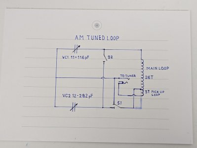
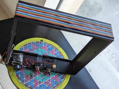
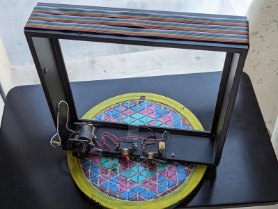
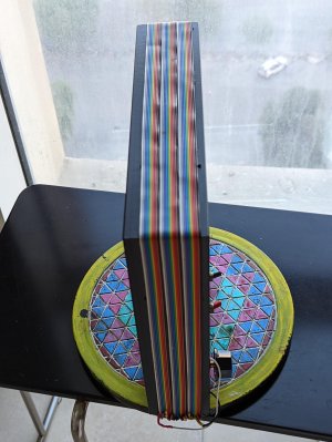
I do not have space for large loops that would be ideal. So settled for a 26cm x 26cm IKEA picture frame to make the inductor. 26 turns formed from an old ribbon cable. Had to solder one end of each wire to one of next wire and so on to make a helical coil.
Formula used is UMC-EMC lab formula with an online calculator at https://earmark.net/gesr/loop/
Could have used normal enamelled or insulated 22AWG wire but fixing on the frame would have been a chore. The ribbon cable was fixed using double side adhesive tape.
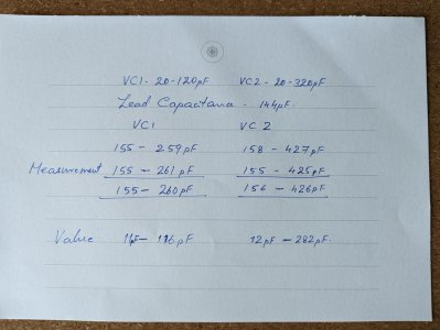
Used a 2 gang variable capacitor VC1 20-120pf, VC2 20-320pf to tune the loop. VC1 is always connected with VC2 switched for lower end of AM band though calculator says VC1 is enough. Parasitic capacitors and inter turn capacitance of the cable may be affecting.
Still the loop makes a marked difference when listening to distant stations as in the video.
For tuners add one more turn inside the frame of main loop or wind it before sticking the main loop and connect one end to the ground point of the variable cap. Connect the other end of this pickup loop to AM antenna in of the tuner and the ground point to the ground of tuner.


