Can Some One Verify my PCB with the Schematic

Hi Sadik,

the best replacements could be:

1. 2SC1775A - 2SC/KSC1845(preferred),2N5551
2. 2SA872A - 2SA/KSA992(preferred),2N5401
3. 2SA634 - BD140,BD442,TIP32C,KSA940(preferred)
4. 2SC1096 - BD139,BD441,TIP31C,KSC2073(preferred)

all are available locally, and you can also order from RS components India, they have decent price and dont charge for shipping.


Regards,
Aniket

I Whole heartedly thank you Aniket.. U made my Day...Thankx a lot once again.

Sadik

I know it OT, but just wanted to show you guys a quick one created using KiCad. I like this tool but its a bit buggy atleast in Windows 10.

View attachment 21451

I Dont know about Kicad (never used it). For me its seems Diptrace is more user friendly.

Sadik
 
Last edited by a moderator:
I Whole heartedly thank you Aniket.. U made my Day...Thankx a lot once again.

Sadik
Dear Mr Sadik,
Congratulations for your fantastic job!
I'm a newbie, and would like to build a hiraga Class A amplifier. Do you sell PCBs for assembly? Can I use a fully regulated power supply whith only one transformer for both amplifiers?
Thnk you very much!
Nilton
 
Hi Mr. Nilton,

I have followed the Schematic and power-supply from below link.
diyaudioprojects

Dann has mentioned the Power supply requirement also. I would suggest you that if you are new in this, then it will be a very difficult task to get this amp running. There are too may factors affecting the performance like, bias setting, DC offset, Ripple Noise etc etc.

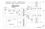
This PCB is very simple and may look like a budget friendly project, but note the Power supply and huge heat-sinks are most expensive part of this project. It needs 1.2 Farad ( 12,00,000 uF ) of capacitance bank and (minimum) 500VA transformer for both channels.

Only few peoples around world have made this amplifier with different power supplies, you can check the threads on diyaudio.com for additional information.

I wish all the best for your project.
Dear Sadik,
Thanks for the advises. This is a very big amp, but I found a lot of small PCBs from 8w to 15w, like Jims Audio Le Monstre ones. Do you think it is a easily and safety option for a beginner?
Im not able to build a power supply like yours, so Im wondering to use a symmetrical stabilized psu to build a small amp. Do you think I can get real Class A sound from them?
Tks!
Nilton

You will not get the right amount of Bass if you compromise on Power Supply Bank.
 
Hello Mr. Sadik,

After some time researching, with the help of some people, I decided to go ahead with the Le Monstre project.

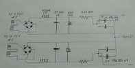
I intend to build a choke input source, with 1 Hammond 185G24 transformer for each channel, with Ixys 55-06NO7 rectifying bridges and Lundahl LL2771 chokes (700mH 2A parallel coins).

I made a drawing of the scheme and I will be very grateful if you can verify that the connections are correct, or if it is necessary to make any corrections.

Thank you very much, and all members omments will be very appreciated!

Rgds
Nilton
 

Attachments

  • Le Monstre PS.jpg
    Le Monstre PS.jpg
    1,023.8 KB · Views: 9
Hello Mr. Sadik,

After some time researching, with the help of some people, I decided to go ahead with the Le Monstre project.

I intend to build a choke input source, with 1 Hammond 185G24 transformer for each channel, with Ixys 55-06NO7 rectifying bridges and Lundahl LL2771 chokes (700mH 2A parallel coins).

I made a drawing of the scheme and I will be very grateful if you can verify that the connections are correct, or if it is necessary to make any corrections.

Thank you very much, and all members omments will be very appreciated!

Rgds
Nilton
Sorry,
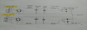
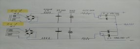
Corrected drawing...
 

Attachments

  • Le Monstre Dual PS.jpg
    Le Monstre Dual PS.jpg
    711.7 KB · Views: 10

NSacchetti.
I am also total newbie when it comes to schematics But do check where transformer Center Tap is connected. Some experts will soon comment. Do not proceed untill 100 % sure.
Regards
 
Sorry,
Corrected drawing...
Sorry Brother I am no expert in this. You can try to post on diyaudio forum there are many experts there. By profession i am mech engineer and i just follow kits to make amplifiers which are well documented.
 
Nice first effort. I might be missing something (Top Layer?), but shouldn't the speaker be connected between the emitters of the output transistors? I can't see this on the pcb.

Cheers,
~hp
 
Nice first effort. I might be missing something (Top Layer?), but shouldn't the speaker be connected between the emitters of the output transistors? I can't see this on the pcb.

Cheers,
~hp
Yes Friend. Our FM @Aniket helped me to get this amplifier working. Each and every error was sorted out by him. He also guided me for the replacement transistors. And today we both are best buddies.
 
Sorry,
Corrected drawing...
Dear Mr. Aniket,

Could you pls take a look on my Choke Input power supply drawing and let me know if it is 100% correct? Anny comment from you will be very appreciated.

Thank you very much!
Nilton
 

Attachments

  • Le Monstre Dual PS.jpg
    Le Monstre Dual PS.jpg
    711.7 KB · Views: 5
Back
Top